
Still I am far away then the usual range of 600 to 700 ppm. Before you start the programming, first of all, make sure you download the necessary libraries; otherwise, you wont be able to display anything on your Oled display module. // Library will draw what it can and the rest will be clipped. Great workout, even i am having same problem. The formula to calculate the resistance of the sensor is wrong. Now we will learn how to connect and code an I2C OLED display with an Arduino microcontroller board and we will also learn how to write a simple code to display a message on your OLED screen. So basically we will be making the Carbon Dioxide Parts per Million Meter. For this Oled display module you will need to install two libraries which are: Now to install these libraries go to the sketch click on the include library and then click on the manage library, Now just write the library name and install it. Copyright 2022Circuit Digest. And also, for the schemetic diagram of the gas sensor, do you solder the resistor to both analog and ground wire? And print the CO2 Values on OLED Display using the display.println() function. If I do, then (1) do I have to change anything in the .h file and (2) do I need to recalibrate? If you had to power it down after the burn-in then calibration can be done after 1 hour power-on. The MQ-135 sensor is usually used to measure the level of CO2, Benzene, Sulfide or Ammonia in the air.
Arduino NRF24 remote

Submitted by M Lakshaga Jyothi on Wed, 07/14/2021 - 10:28. Th vin: https://github.com/GeorgK/MQ135. I have a couple questions concerning your tweaks ! Go to sketch click on the include library and click on the zip file and insert the zip file. Hi !
I also had problems with R0. Hi, I would like to know how do you replace the load resistor from 1K ohms to 22 K ohms. I was also wondering, what exactly is Rzero? For that, connect the Arduino to the laptop, select the Board and Port, and hit the upload button. Or I am using a MQ-135 sensor with a bad response curve. When changing the value of RLOAD to 1.0 you do not need the 22K resistor. Also take care that your temperature sensor is not to close to the MQ135, rob now i need to print these ppm values to my 162 LCD display with i2c module give me another code with lcd.print. ylngc th hiu lkhi lng,th tch, s ht (smol), Khi dng cn ch rlngl g. hardware by purchasing products from Adafruit!
// display.display() is NOT necessary after every single drawing command, // unless that's what you wantrather, you can batch up a bunch of, // drawing operations and then update the screen all at once by calling.

This code is for measuring Carbon Dioxide (CO2), This Code for measuring Acetone(C3H6O) with MQ-135 Sensor. #define RLOAD 22.0 // display.display(). The complete code for interfacing MQ-135 Sensor with Arduino is given at the end of the document.
mq135 atmospheric adjust Apart from CO2, we have also measured the concentration of LPG, Smoke, and Ammonia gas using Arduino. First I started with a very simple analog read to check the values in my computer/hobby room with a CO2 ppm around 650. The Oled display module I am using is SSD1306 which i have been using for quite a long time and seriously this is my favorite one. You only need to change line 25 (RLOAD) in the .h file to adjust the value. The 5V pin on the arduino comes directly from your USB port power. Here we are explaining some important parts of the MQ135 Arduino code. Now scroll down and replace the ATMOCO2 value with the current Atmospheric CO2 that is 411.29. I have a similar MQ135 board (the PCB and resistor values seem to be the same) and the sensor doesnt seem to be sensitive to anything (the analog output doesnt seem to change when exposed to C02, lighter gas, alcohol or smoke). The raw value measured with the arduino was now 241.
mq135 ccl harmful 13 28 for CO2 ppm of about 500 2000 gives a resolution of about 100ppm/value measurement A bright light is produced when an electric current is applied to these films. But when breath out right in front of sensor, suddenly the reading rises up closing to 170-220 PPM. After installing the libraries to Arduino IDE, start the code by including the needed libraries files. You can also learn more about the basics of OLED display and its types by reading the linked article. Please show that through some video or demonstrations. The OLED consists of four pins which are: The SCK is the clock pin, SDA is the data pin, VCC is the power pin and GND is the ground pin. I have been doing Job in UAE as a site engineer in an Electrical Construction Company.
I currently use 10.0 as RLOAD, because thats what the library I use came with (I am using the library in link 2 below, is that a good one?).
Tng quan v kin trc ARM v h vi iu khin STM32, PIC18F4550 LCD2004 DS1307 RTC, cm bin DHT22 trn CCS C, Module o in AC a Nng Giao Tip UART PZEM004T, KIT STM32F4 Discovery Bi 5: B nh thi (TIMER), [Su tm] Vi lu khi thit k mch in nhiu lp, [Arduino IDE] Lp trnh STM32F103C8T6 vi DHT11 hin th LCD, 11 mo layout PCB cho tn hiu tc cao high speed, Pht hin im khng ca in xoay chiu vi PIC16F877A, https://technologyitemsforcollege.blogspot.com, BST1: TIMER 0 PIC16F877A vi trnh bin dch XC8, https://www.facebook.com/pages/category/Health---Wellness-Website/Vital-flow-reviews-102135748499657/, o tc ng c dng encoder vi Arduino, Mt s khi nim cn bn v GPIO ca Vi iu khin push-pull v open-drain, Thit t Digital Pins nh l INPUT, INPUT_PULLUP, v OUTPUT, [Arduino]Giao tip nhiu cm bin nhit DS18B20, Chn chn mn hnh lm Slave khi giao tip SPI, in tr ti: Thay i c (2kOm -> 47kOm), Cng sut tiu th ca heater: Nh hn 800mW, Nng pht hin ca mt s cht: 10 300 ppm NH3, 10 1000 ppm Benzen, 10 300 ppm Alcol. The earths Atmospheric CO2 level is increasing day by day. Gii thiu ESP32 vi ADC ni
Dear Mr Rob, I am working on a project which uses MQ 135 sensor board. I see that my RL is 1K ohm. 3 pins are required to interface (two I2C and one reset).

I just have a noob question, After i have burned it for 24 hrsHow I will get the RZero value?? Do you have any why I am not getting any meaningful reading from it?
arduino co2 sensor application notes connect uno update k30 sensors senseair mega2560 rewritten microcontrollers mega engineering team i was run that program but i get a error message like that gasSensor was not declared in this scope and error in this line of code please help me to solve this float ppm = gasSensor.getPPM(); I just noticed that the following was on 1 line in my example: #include MQ135.h Myself, I stopped publishing articles like this, because people dont do their own research, and I had to answer the same simple questions over and over.


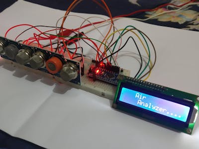
The global average atmospheric carbon dioxide in 2019 was 409.8 parts per million and in October-2020 it is 411.29. Before you jump into the project first play with the code a little, to understand how you can display different texts at different positions. Cant wait to see the results! Look on other sites how to connect the LCD to your board, Your email address will not be published. The measured CO2 concentration values will be displayed on the OLED module and last we will also compare the Arduino MQ-135 sensor readings with Infrared CO2 sensor readings. Mch iu khin:
esp8266 rauch benzol nox Finally, I calculate the PPM value by averaging retrieved values over 30 seconds, with 2 measurements per second.
Thanks for the excellent writeup.
mq135 The MQ-135 sensor is to sensible for other gasses in the air so that is not possible to get good values for CO2 from it.
arduino Then open your serial monitor and wait for some time (preheat process), then you'll see the final data. Just a quick follow up, where exactly do I put the 22K resistor?
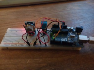
mq sensor arduino monoxide carbon circuit hydrogen gas built pinout dout aout use leads there Arduino Gas leakage Detection with SMS Alert. Thank you. Thanks for your effort. MQ-135 Gas Sensor and OLED Display module both are powered with +5V and GND.
mq5 breadfruit monoxide mq7 Hi sir, so float MQ135::getResistance() { So in the lower ppm part the resolution is much better, but above the 1000ppm the resolution will be very low. Hey rob, Suman. Via bao gm 3 thnh phn:
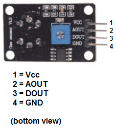
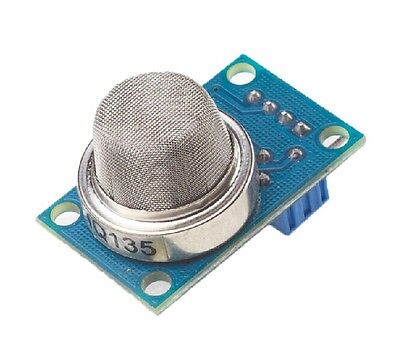
It can work on three different communications Protocols: SPI 3 Wire mode, SPI four-wire mode, and I2C mode. Will resistance add up to 23K if I do that? Without any further delay lets get started!!! On the serial monitor, you can see the values of the analog pin being detected. I think it will better to change that value to 403, as 397 was the lowest CO2 a few years ago. But, before I am going to explain the wiring first lets take a look at the MQ135 Sensor.
Im wondering if it could be due to one of the following: The last picture on Amazon shows that RLOAD is 1K (it has text 102 on it) and what changes I have to do. And may i know how to set the RO since every-time the value is varies. This site uses Akismet to reduce spam. Can I ask, if the voltage is 3.3 V, do I need to modify the library somwhere? In our previous project, we used the Gravity Infrared CO2 sensor to measure the CO2 concentration in air. Kindly suggest? with contributions from the open source community. I get this error when I tried to run the script "TypeError: My name is Shahzada Fahad and I am an Electrical Engineer. The connection of the I2C Oled display module with the Arduino remains exactly the same and we dont need to change any wires, we can now add our MQ135 Sensor with the Arduino Uno or Arduino Nano to find the CO2 Concentration.

/ (float)val) 1.) I had bought 3 MQ-135 gas sensors on AliExpress to test if it is possible to measure CO2 with them. It probably is to responsive to other gases in my surroundings. Lowest CO2 now a days will be 403 in the forests, if you live in a city with high car pollution your lowest CO2 will be around 410-425. Are these numbers OK, or are the optimal numbers different (e.g. MQ-135 Gas Sensor is an air quality sensor for detecting a wide range of gases, including NH3, NOx, alcohol, benzene, smoke, and CO2. The screw on the back is only to adjust the on/off point of the digital output. // drawing commands to make them visible on screen! If you already know how to interface the SDD1306 I2C Oled display module with the Arduino then you can jump to the end. The Arduino board has SDA at pin number A4 and SCK at pin number A5. If your display behaves in an abnormal way and if you cant see anything then you should read my article on, Connect the VCC of the MQ135 Sensor with the 5V of the Arduino, Connect the gnd of the MQ135 with the ground of the Arduino, Connect the analog pin of the MQ135 with the A0 of the Arduino, Connect the anode of the led with the 220-ohm resistor at digital pin number 9, Connect the cathode of the Arduino with the ground of the Arduino, * Atmospheric CO2 Level..400ppm, * Average indoor co2.350-450ppm, * Maxiumum acceptable co2..1000ppm, * Dangerous co2 levels.>2000ppm, #include
//I2C for OLED, #include //grafix library for OLED, #include //OLED Driver, #define anInput A0//analog feed from MQ135, #define digTrigger 2//digital feed from MQ135, #define co2Zero 55//calibrated CO2 0 level, #define led9//led on pin 9, #define OLED_RESET 4//OLED reset on lin 4, Click to share on Twitter (Opens in new window), Click to share on Facebook (Opens in new window), Click to share on WhatsApp (Opens in new window), Click to share on Telegram (Opens in new window), Click to share on Tumblr (Opens in new window), Click to share on LinkedIn (Opens in new window), Click to share on Reddit (Opens in new window), Click to share on Pinterest (Opens in new window), Click to share on Pocket (Opens in new window), Click to share on Skype (Opens in new window). // Calibration resistance at atmospheric CO2 level. or I have this model (see link 1 below), how do I know the RLOAD value of this model? (adsbygoogle = window.adsbygoogle || []).push({}); *Please Note: These are affiliate links.  I am using same library, and i am getting 0.5 ppm. Hey everyone, once we have applied 5v for more than 24 hours in second time how much time we should wait for good result??? Cm bin ny c th nhn bit c cc cht kh nh NH3, Nox, Ancol, Benzen, Khi, gas, CO2 a s kh n nhn bit u l kh tp cht v khng c li cho sc khe nn chnh v vy ngi ta gi n l cm bin cht lng khng kh. The threshold values of the C02 are as follow: We will require three libraries for interfacing OLED with Arduino which we have explained above in detail, // LIBRARIES, #include //I2C for OLED, #include //grafix library for OLED, #include //OLED Driver, The data from the MQ135 Sensor is taken from the analog pin of the MQ135 which is connected with A0 of the Arduino and is stored in variable anInput, #define anInput A0 //analog feed from MQ135, #define digTrigger 2 //digital feed from MQ135, Now this is the atmospheric value of carbon dioxide, #define co2Zero 55 //calibrated CO2 0 level, #define led 9 //led on pin 9, #define OLED_RESET 4 //OLED reset on lin 4, // LIBRARY CALL, Adafruit_SSD1306 display(OLED_RESET); //create instance of OLED called display, // SETUP, pinMode(anInput,INPUT); //MQ135 analog feed set for input, pinMode(digTrigger,INPUT); //MQ135 digital feed set for input, pinMode(led,OUTPUT); //led set for output, Serial.begin(9600); //serial comms for debuging, display.begin(SSD1306_SWITCHCAPVCC, 0x3C); //begin display @ hex addy 0x3C, display.display(); //show buffer, display.clearDisplay(); //clear buffer, // MAIN LOOP, This integer will save the concentration of the of the carbon dioxide, int co2now[10]; //int array for co2 readings, int co2raw = 0; //int for raw value of co2, The compensated value of the carbon dioxide will be saved in co2comp, int co2comp = 0; //int for compensated co2, int co2ppm = 0; //int for calculated ppm, intzzz = 0; //int for averaging, intgrafX = 0; //int for x value of graph, display.clearDisplay(); //clear display @ beginning of each loop, Now through this loop we will collect the samples of the carbon dioxide in 2 seconds, for (int x = 0;x<10;x++){ //sample co2 10x over 2 seconds, After filling up of the array then we are going to add the sample together we will create another for loop, for (int x = 0;x<10;x++){ //add samples together, Now in the zzz variable, we have added all the samples of the carbon dioxide we will divide it by 10 to obtain the average value, co2raw = zzz/10; //divide samples by 10, co2comp = co2raw co2Zero; //get compensated value, As we know that analog input create value are from 0 to 1023 we will used the map function the minimum value will be 400 and the maximum value will be 5000 for the ppm value, co2ppm = map(co2comp,0,1023,400,5000); //map value for atmospheric levels, display.setTextSize(2); //set text size, display.setTextColor(WHITE); //set text colo, display.setCursor(0,0); //set cursor, display.println(CO2 Level); //print title, display.println( ); //skip a line, display.print(co2ppm); //print co2 ppm, display.print( PPM); //print units, grafX = map(co2ppm,0,1000,0,127); //map value to screen width, display.fillRect(0, 52, grafX, 10, WHITE); //print graph 400min 1000max, display.display(); //show the buffer, if(co2ppm>999){ //if co2 ppm > 1000, digitalWrite(led,HIGH); //turn on led, else{ //if not, digitalWrite(led,LOW); //turn off led. I connected the 5V power to the sensors and let them alone for 24 hours to burn in. Required fields are marked *. Conductive barrel: L khoan c m dn in
So CO2 level monitoring has also started to gain importance. Before, we find the concentration of the Carbon Dioxide or the CO2 level first; lets learn how to interface the OLED display module with the Arduino. Found out that the resistor towards ground was just 1K ohm, after replacing the resister with one 22K ohm the results were getting much better. After these 24 hours I checked the values measured with the above little test program. MQ135 library can be downloaded from here. The Arduino sends outthe following output to the serial port. The next morning ppm was down to 500 according to the NETATMO, but the arduino showed a ppm of 600. Without changing the formula it was reading 0.5 to 0.4 ppm, and now after changing the formula, as suggested by you, ppm is in the range of 36 to 38. That tiny resistor needs to be removed, and then a new 22K resistor needs to be added on the same place. int val = analogRead(_pin); mq135 ambiental electronperdido sensores I mean what is the code for getting the RZero after the burnout? -My arduino uno 5V pin cant provide enough power for the MQ135. Very interesting & neat project.
I am using same library, and i am getting 0.5 ppm. Hey everyone, once we have applied 5v for more than 24 hours in second time how much time we should wait for good result??? Cm bin ny c th nhn bit c cc cht kh nh NH3, Nox, Ancol, Benzen, Khi, gas, CO2 a s kh n nhn bit u l kh tp cht v khng c li cho sc khe nn chnh v vy ngi ta gi n l cm bin cht lng khng kh. The threshold values of the C02 are as follow: We will require three libraries for interfacing OLED with Arduino which we have explained above in detail, // LIBRARIES, #include //I2C for OLED, #include //grafix library for OLED, #include //OLED Driver, The data from the MQ135 Sensor is taken from the analog pin of the MQ135 which is connected with A0 of the Arduino and is stored in variable anInput, #define anInput A0 //analog feed from MQ135, #define digTrigger 2 //digital feed from MQ135, Now this is the atmospheric value of carbon dioxide, #define co2Zero 55 //calibrated CO2 0 level, #define led 9 //led on pin 9, #define OLED_RESET 4 //OLED reset on lin 4, // LIBRARY CALL, Adafruit_SSD1306 display(OLED_RESET); //create instance of OLED called display, // SETUP, pinMode(anInput,INPUT); //MQ135 analog feed set for input, pinMode(digTrigger,INPUT); //MQ135 digital feed set for input, pinMode(led,OUTPUT); //led set for output, Serial.begin(9600); //serial comms for debuging, display.begin(SSD1306_SWITCHCAPVCC, 0x3C); //begin display @ hex addy 0x3C, display.display(); //show buffer, display.clearDisplay(); //clear buffer, // MAIN LOOP, This integer will save the concentration of the of the carbon dioxide, int co2now[10]; //int array for co2 readings, int co2raw = 0; //int for raw value of co2, The compensated value of the carbon dioxide will be saved in co2comp, int co2comp = 0; //int for compensated co2, int co2ppm = 0; //int for calculated ppm, intzzz = 0; //int for averaging, intgrafX = 0; //int for x value of graph, display.clearDisplay(); //clear display @ beginning of each loop, Now through this loop we will collect the samples of the carbon dioxide in 2 seconds, for (int x = 0;x<10;x++){ //sample co2 10x over 2 seconds, After filling up of the array then we are going to add the sample together we will create another for loop, for (int x = 0;x<10;x++){ //add samples together, Now in the zzz variable, we have added all the samples of the carbon dioxide we will divide it by 10 to obtain the average value, co2raw = zzz/10; //divide samples by 10, co2comp = co2raw co2Zero; //get compensated value, As we know that analog input create value are from 0 to 1023 we will used the map function the minimum value will be 400 and the maximum value will be 5000 for the ppm value, co2ppm = map(co2comp,0,1023,400,5000); //map value for atmospheric levels, display.setTextSize(2); //set text size, display.setTextColor(WHITE); //set text colo, display.setCursor(0,0); //set cursor, display.println(CO2 Level); //print title, display.println( ); //skip a line, display.print(co2ppm); //print co2 ppm, display.print( PPM); //print units, grafX = map(co2ppm,0,1000,0,127); //map value to screen width, display.fillRect(0, 52, grafX, 10, WHITE); //print graph 400min 1000max, display.display(); //show the buffer, if(co2ppm>999){ //if co2 ppm > 1000, digitalWrite(led,HIGH); //turn on led, else{ //if not, digitalWrite(led,LOW); //turn off led. I connected the 5V power to the sensors and let them alone for 24 hours to burn in. Required fields are marked *. Conductive barrel: L khoan c m dn in
So CO2 level monitoring has also started to gain importance. Before, we find the concentration of the Carbon Dioxide or the CO2 level first; lets learn how to interface the OLED display module with the Arduino. Found out that the resistor towards ground was just 1K ohm, after replacing the resister with one 22K ohm the results were getting much better. After these 24 hours I checked the values measured with the above little test program. MQ135 library can be downloaded from here. The Arduino sends outthe following output to the serial port. The next morning ppm was down to 500 according to the NETATMO, but the arduino showed a ppm of 600. Without changing the formula it was reading 0.5 to 0.4 ppm, and now after changing the formula, as suggested by you, ppm is in the range of 36 to 38. That tiny resistor needs to be removed, and then a new 22K resistor needs to be added on the same place. int val = analogRead(_pin); mq135 ambiental electronperdido sensores I mean what is the code for getting the RZero after the burnout? -My arduino uno 5V pin cant provide enough power for the MQ135. Very interesting & neat project. 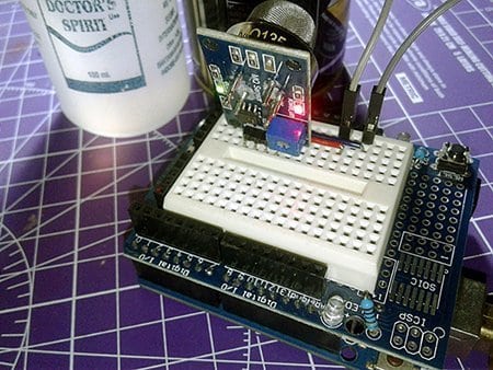

 This will calibrate the sensor with the reference of 397.13ppm (ATMOCO2 line 42 .h file) hi there, If not what changes do I have make in the Library? lokman
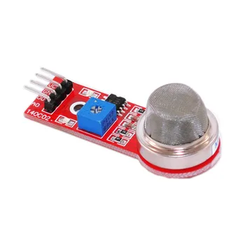
 Adafruit invests time and resources providing this open, source code, please support Adafruit and open-source. The Analog Out pin of the MQ-135 sensor is connected to the A0 pin of Arduino Nano. return ((1023. esp8266 alkohol mq135 nh3 rauch ppm = 1/1 000 000 = 10-6. CO2 Concentration, CO2 PPM, or CO2 Levels using MQ135 Sensor & Arduino, Connect the SDA pin of the OLED with the pin number A4, Connect the SCK pin of the OLED with the pin number A5, Connect the VCC pin of the OLED with the 5V of the Arduino, Connect the ground pin of the OLED with the ground of the Arduino, Now click on files and in files click on examples and in examples select, /**************************************************************************, This is an example for our Monochrome OLEDs based on SSD1306 drivers, ------> http://www.adafruit.com/category/63_98, This example is for a 128x32 pixel display using I2C to communicate.
 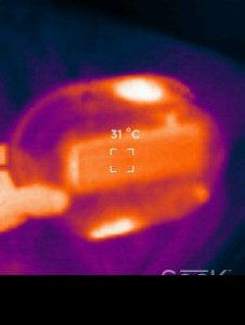 The next day I have tested the same with another MQ-135, but the results were about the same. I think it will better to change that value to 403, as 397 was the lowest CO2 a few years ago. Since the OLED Display module uses SPI communication, we have established an SPI communication between the OLED module and Arduino Nano. -The stock load resistor is too small.
Then define the SPI communication pins where OLED Display is connected. Measuring CO2 Concentration in Air using Arduino and MQ-135 Sensor, AMF Series 18/24/36 W Medical AC-DC Adaptors, TPP 180 and TPI 180 Medical and Industrial AC/DC Power Supplies, NTS/NTU Series Reliable, Safe, and Durable DC-AC Pure Sine Wave Inverters, IsoMOV Series Hybrid Protection Component. These libraries can be downloaded from the Library Manager in the Arduino IDE and install it from there. (Airport and highway). Tuy nhin chng ta Bootloader l mt chng trnh nh c np sn vo chip vi iu khin trn Arduino, nh bn lp trnh cho Arduino mt Tch hp Robot 2 bnh t cn bng vi 2 cm bin khong cch v module RF NRF24L01.
The next day I have tested the same with another MQ-135, but the results were about the same. I think it will better to change that value to 403, as 397 was the lowest CO2 a few years ago. Since the OLED Display module uses SPI communication, we have established an SPI communication between the OLED module and Arduino Nano. -The stock load resistor is too small.
Then define the SPI communication pins where OLED Display is connected. Measuring CO2 Concentration in Air using Arduino and MQ-135 Sensor, AMF Series 18/24/36 W Medical AC-DC Adaptors, TPP 180 and TPI 180 Medical and Industrial AC/DC Power Supplies, NTS/NTU Series Reliable, Safe, and Durable DC-AC Pure Sine Wave Inverters, IsoMOV Series Hybrid Protection Component. These libraries can be downloaded from the Library Manager in the Arduino IDE and install it from there. (Airport and highway). Tuy nhin chng ta Bootloader l mt chng trnh nh c np sn vo chip vi iu khin trn Arduino, nh bn lp trnh cho Arduino mt Tch hp Robot 2 bnh t cn bng vi 2 cm bin khong cch v module RF NRF24L01. 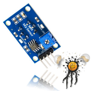 For that, open the Arduino IDE and go to Sketch < Include Library < Manage Libraries. With the 1K resistor the readings are not sensitive and just changing a little bit while the CO2 is changing a lot. Solutions for 5G, smart home, industrial, automotive, healthcare, and agricultural IoT applications, TRACO Power's 180 W power supplies are offered in ultra-compact open-frame and enclosed packages, MEAN WELL's sine wave inverters offer industrial-grade high reliability, safety, and quality, Bourns' hybrid protection component combines both MOV and GDT technologies into a single component. IP22 rated medical & home-healthcare 18/24/36W AC-DC adaptors with interchangeable AC plugs. With 1 sensor I measured different voltages on the analog port with same amount of CO2. Schematic
Please explain this i have searched many blogs and articles for this. But if you track your PCB traces to find the value of your RL in the board, you can see a 1K (102) load resistor. And in the last, call the display() method to display the text on OLED Display. meaning that the equation should be changed to this instead of 5-1? In this project, were using a 12864 SPI OLED display. Or am I misunderstanding the issue completely? For this project, we are using aMonochrome 7-pin SSD1306 0.96 OLED display. Submitted by Ihaiz on Thu, 05/06/2021 - 13:48. I was just wondering how the corrected R0 which takes temperature and humidity into account fits in here. Do I need to remove the on-board resistor and replace it with a 22K one (and I dont have the means to do that), or can I use breadboard to just add a 22K resistor? It does nothing to the analogue output. If you continue to use this site we will assume that you are happy with it. Robot
My Hobbies are * Watching Movies * Music * Martial Arts * Photography * Travelling * Make Sketches and so on if you enjoy our content, please support our site by disabling your adblocker. The circuit diagram for the MQ-135 board is given below: The load resistor RL plays a very important role in making the sensor work.
I am from india Bangalore, and my area CO2 level is 390 ppm but my mq135 show not even near to it. It is not an easy job, but can be done with the correct equipment. You MUST call display() after. // select the input pin for the MQ-135 sensor.
For that, open the Arduino IDE and go to Sketch < Include Library < Manage Libraries. With the 1K resistor the readings are not sensitive and just changing a little bit while the CO2 is changing a lot. Solutions for 5G, smart home, industrial, automotive, healthcare, and agricultural IoT applications, TRACO Power's 180 W power supplies are offered in ultra-compact open-frame and enclosed packages, MEAN WELL's sine wave inverters offer industrial-grade high reliability, safety, and quality, Bourns' hybrid protection component combines both MOV and GDT technologies into a single component. IP22 rated medical & home-healthcare 18/24/36W AC-DC adaptors with interchangeable AC plugs. With 1 sensor I measured different voltages on the analog port with same amount of CO2. Schematic
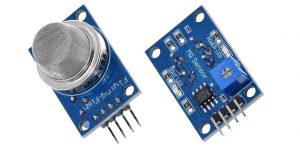
Please explain this i have searched many blogs and articles for this. But if you track your PCB traces to find the value of your RL in the board, you can see a 1K (102) load resistor. And in the last, call the display() method to display the text on OLED Display. meaning that the equation should be changed to this instead of 5-1? In this project, were using a 12864 SPI OLED display. Or am I misunderstanding the issue completely? For this project, we are using aMonochrome 7-pin SSD1306 0.96 OLED display. Submitted by Ihaiz on Thu, 05/06/2021 - 13:48. I was just wondering how the corrected R0 which takes temperature and humidity into account fits in here. Do I need to remove the on-board resistor and replace it with a 22K one (and I dont have the means to do that), or can I use breadboard to just add a 22K resistor? It does nothing to the analogue output. If you continue to use this site we will assume that you are happy with it. Robot
My Hobbies are * Watching Movies * Music * Martial Arts * Photography * Travelling * Make Sketches and so on if you enjoy our content, please support our site by disabling your adblocker. The circuit diagram for the MQ-135 board is given below: The load resistor RL plays a very important role in making the sensor work.
I am from india Bangalore, and my area CO2 level is 390 ppm but my mq135 show not even near to it. It is not an easy job, but can be done with the correct equipment. You MUST call display() after. // select the input pin for the MQ-135 sensor.  The complete MQ135 Air Quality Sensor Arduino Code and working video are given below. The more measurement you take the better it will be. In my room s the real ppm was about 770 ppm according to my NETATMO. yes, just connecting it to the power will do. I may make a commission if you buy the components through these links. Then in the next line, call the gasSensor.getPPM() to calculate the PPM values. This is no good of course, so something must go wrong in the calculations in the MQ135 library. it may take more or less in different situations. If you have no experience with soldering you better leave the 1K resistor and change the value in the library. // Not all the characters will fit on the display. The pins and its functions are explained in the table below: Acts as the clock pin.
  BSD license, check license.txt for more information, All text above, and the splash screen below must be, **************************************************************************/, #define SCREEN_WIDTH 128 // OLED display width, in pixels, #define SCREEN_HEIGHT 32 // OLED display height, in pixels, // Declaration for an SSD1306 display connected to I2C (SDA, SCL pins), #define OLED_RESET 4 // Reset pin # (or -1 if sharing Arduino reset pin), #define NUMFLAKES 10 // Number of snowflakes in the animation example, // SSD1306_SWITCHCAPVCC = generate display voltage from 3.3V internally, // Show initial display buffer contents on the screen --.
Sitemap 18