energy operated Meter Connection Diagrams.
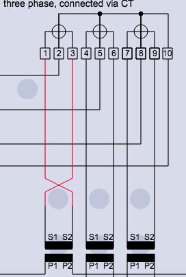
ct connection diagram PAC3200 Route CT wires through conduit to the PVS5x. Circuit diagram of PF relay. Please see pages 4-9 to 4-10 for the diagram. This manual includes complete information to install, configure, and maintain the kV2c socket meter from GE. Meter Installation Manual-HXE310 10 / 18 Fig 5.2 CT/PT connection 6 Dimension .
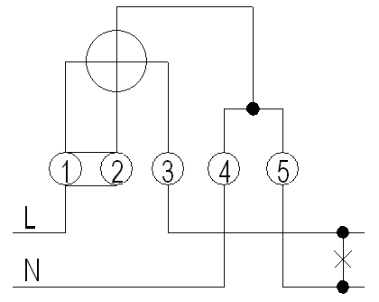
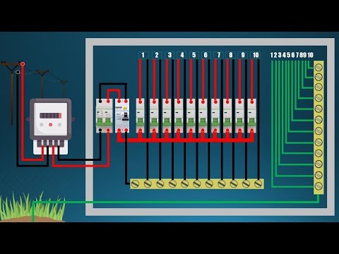
Energy Meter Installation diagram 5.2 Wiring diagram This power meter supports the two connection modes of direct connecting or connecting via a current transformer CT. When the generator requests PG&E owned metering (i.e., CAISO and/or customer owned meter), PG&E will perform the wiring work and charge the customer accordingly. In the above diagram i shown how to wire or instill the three phase energy meter. Meter connection step To grid-L To inverter-L o grid-N To inverter-N 485B 485A 1 7 11 3 6 9 1615 4 3 1 4 7 11 6 9 Meter connection diagram Electrical grid Home Electric meter, Three phase meter Load Meter connection L N Communication interface bewteen inverter and meter is RS485 with a RJ45 connector.
UNDERGROUND SERVICE INDEX JUN 20 SECTION Energy Meter Ct Connections Model 104 High Reliability Energy Meter - Wiring Diagram -EML Precision eml-precision.com.
Meter Wiring Diagram Complete GE Manual for 4 IS 9000 Basic Environmental testing procedure for electrical and electronic items. Three Phase Ct Energy Meter Connection Diagram.
Premier 300 A CT meter is simply a meter that is used in conjunction with instrument transformers known as current transformers.
Always follow your Company's internal standards.
CT Method 7: Using Modern Testing equipment: Some of the modern testers are used to identify the CT polarity in offline. A9MEM3200 iEM3200 energy meter CT Schneider Electric. Supported System Types The Energy Meter Series has a number of different possible system wiring configurations (see Section 4, Wiring). Wiring Diagrams.
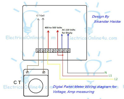
Milbank The manual already have an example of the wiring diagram for Dual phase (3 wire) and single phase (2 wire). Connect a 0.1 ohm Action-Pak AC current transducer in the CT circuit, in series with your meter, and let it report the resulting 0 to volt AC signal to your PLC analog input. A high-performance measurement solution for intelligent energy management in PV systems with SMA devices.
Energy Meter Ct Connections The MT174 electronic three-phase meters are designed for measurement and registration of active, reactive and apparent energy and demand in three-phase four-wire networks. Now that we know what CTs and PTs are, we can talk about meter multipliers.
CT DIY Energy Savings Tools; Home Energy Savings; Business Energy Savings CT-Meter-Can-and-Cabinet. wiring diagram pemasangan ct Cara Memasang Kwh Meter Listrik 3 Phase Guru.
 wiring phase transformer current diagram single wire watt meter sample three meter wiring diagram
 Any bond between the meter enclosure and joint users that interferes with removing the cover on the meter box is a violation of NEC 250.94 (3). This manual includes basic wiring diagrams for use during installation. A CT having more than one core and more than one secondary winding is known as a multi-core CT (for example, a CT having metering and protection cores). Energy - The integral of active power over time.
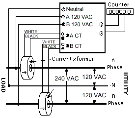
compiled Section 5.4 Main power & sensor wiring diagrams 13 Section 5.5 Line voltage/current sensor diagnostics 14 Section 5.6 RS-485 wiring 15 Section 5.7 Modem wiring 16 Section 6.0 Con guring the meter using E-Mon Energy 17 Section 7.0 Preventative/scheduled maintenance 17 The current wire connects to X1 on the CT. Three wire circuit voltages may be 120240 volt line-groundline-line or 240480 volt line-groundline-line. 325 Guide on A.C.Static Electrical Energy Meters - Specification (latest amendment).
 wiring diagrams
 meter phase wiring wire electric diagram base box service electrical delta neutral pole mobile amp 200 wired without wye illustration. Consumers Energy will furnish the two-position, horizontal style sockets. Be aware that these are general diagrams using standard test switches which may not match some Utility standards in their configuration and are for reference only. 3 4 energy meter wiring diagram. Connection type CT-operated CT/VT-operated Wiring configuration 3-phase 4-wire 3-phase 3-wire, 3-phase 4-wire Voltage range 230/240 V (P-N) 110 V (P-P), 63.5 V (P-N) Applicable to both LV and HV Form 5S Meter Delta No VT. Form 5S Meter Network. On DC meters these markings refer to positive and negative. This page contains circuit type and wiring diagrams for all the form s of meters sockets and pans. There are self-contained meters. 9 three phase ct pt connected keypad energy meter. 1.2. 47 ways to wire your power meter wrong wiring diagrams bay city metering nyc roughrider electric cooperative forms 6s 36s three phase 4 wye ct diagram oem fuse box form 9s trusted can and cabinet baldwin emc 5 2 element with residential watt hour lt ac four panel data energymeterwiringdiagram 3 connection for l t whole make the most of. Also a voltage divider to sense the phase voltage and some kind of power supply, e.g. This flux when links with the discs cause an eddy current to flow in it.
ANSI METER WIRING DIAGRAMS - Glems Standards and Compliance Class Typical Overhead CT Cabinet & Meter Equipment Clearances Wall Mount Above Flood Figure 22.
CT Shorting Block connection - Mike Holt's Forum The principle of working of a 3-phase energy meter is similar to the single-phase energy meter. 1K215133 07/12
wiring diagram 
11030 Cochiti Rd SE. Follow the black lines. Meter constant : 1250/ (external CT ratio x PT ratio) Rs485 port Modbus RTU 2400, 4800, 9600, 19200 bps (site selectable) Wiring Diagram 8. This is 3 phase ct meter connection wiring diagram. The GE manual recommends shorting blocks as an option, but the installation block diagram of the energy meter show 3 completely independent ct's.
phase kwh watt gbodhi If a load greater than 2A is controlled, e.g spa pool, the customer is required to fit an auxilary contactor. current transformer wiring ct phase diagram installation three coil power supply. The meters are provided with both input and output voltage connections which allow up to 32 meters to be daisy-chained to a common supply voltage via the first meter. Form 5S Meter VT. Form 6S Meter No VT.
singele connection mcb Form 3S Meter 2 Wire. The primary of a current transformer typically has only one turn. Albuquerque, NM 87123.
energy meter You have to connect the current transformer to the energy meter. Note: If CTs do not fit in this location, refer to Alternate CT Installation Configurations on other side. EZ Meter manufactures revenue-grade electric Kwh submeters primarily for 2 of the 3 electric submeter markets, as well as corresponding remote communication and enclosures.including multiple meter units (MMU).
Meter Wiring Diagrams For The Northpower Network :: Northpower Connect the white and black CT leads to the corresponding CT input terminals with the white and black dots. DIY Energy Savings Tools; Home Energy Savings; Business Energy Savings CT-Meter-Can-and-Cabinet. kilowatt-hours (kWh). Find Ct Connection Diagram For Energy Meter Manufacturers & Suppliers from China.

as a relay or meter Maintenance > > Recover unknown CT nameplate data > Verify correct wiring and connections > Compare your results with previous results > Create customized reports > Front-panel display of wiring diagrams and step-by-step instructions You have 3 different options for the operation of your CT Analyzer
Puget Sound Energy 2.
Energy Meter Connection Diagram VISIONTEK 37CM Three Phase Electronic Energy Meter is a CT operated trivector meter designed to meetthe energy metering requirements of high power consumers. The ET112 (for single phase max. into the meter.
 How to Find Current Transformer (CT) Polarity
 Add Tip. CT-2M - Wiring Diagram Panel Cutout Details The panel Meter is installed on the cabinets front panel and shall be secured firmly with cabinet using 4 transparent Clips Use 0.5mm2 to 2.5mm2 Cable for Voltage terminal & 3mm2 to 6mm2 cable for Current terminals 4 ac, 3 Phase, 4 Wire Electronic kWH Meter CT-2M -/5A 6400 imP/kWh Sr. No. Calibration Certificate (1) 4.
New Patented Products 3 phase ct Meter Wiring Diagrams. Refer to the connection diagram below: Figure 9: Meter connections. Form 4S Meter.
Energy Meters SMA Energy Meter Advanced Power 3 phase energy meters for transformer connection with M. Electronic polyphase meter Elster.
Technical Specification for Three Phase, Four Wires Figure 5. 1.4.3 Selection and connection of the CTs / Only CTs with voltage output of 0.333 V may be used, which means that the secondary side must have a voltage output of 0.333 V. The CTs primary current should be equal to or greater than the maximum expected AC current from the This document uses an SH5K-20 inverter as an example for explanation. Align the steel core pieces and snap the CTs closed. First Class 3 Phase Energy Meter Connection Diagram With Ct And Pt Timer Switch Without Neutral Pin On House Wiring Of Electrical Main Board Electrical Board Wiring Bangladesh When ct s and pt s are used in a metering installation the installation is known as being transformer rated. New Patented Products 3 phase ct Meter Wiring Diagrams. 31 Connection diagram Shall be provided on terminal cover 32 Initial Startup of meter Within 5 sec after ref voltage is applied to the meter terminal 33 Electric Service Handbook 2022 Non-residential Projects Our commitments to appointments and service We stand behind our service to you.
Sitemap 36