Positive values open the inlet valve (which is controlled by PWM, so analogWrite(0) closes the valve, analogWrite(512) opens it half-way, and so on). Therefore, the sealed output here is actually quite close to my intended application, which will consume little to no air. Could this be used to regulate negative air pressure as well as positive? +1 What is being done here looks very high class. Typically we were using air pressure to drive a piston and generate force to push on something, and had a load cell to sense force and closed the loop around that. Im hoping to get a student to work on improving the control, so Ill add this to the list of things for them to try. Thats a great idea. In short, the requirements for the PCB were: Essentially, Iwant a small, integrated package, but still offer as much flexibility as possible with regards to communication with other components, and choice of valves and sensors. Inline 15below, we have delay(1000), so the loop will repeat every 1 second. Set the regulator so that you can feel air coming out of the board's output. You should To make a long story short, the tiniest lost volume magnetic flap valve I could find over volted so I could operate it faster, using a arduino for command and timing on the inletand a more normal small orifice solenoid valve controlled by the same arduino between the turbo pump and forepump on the outlet, with a high rez a/d on the system pressure sensor I need to power 10 devices that will use no more than Press J to jump to the feed. To test this, Iused a Teensy 3.2 as the "master". So to counteract that, I average out several successive readings, and also only consider changes of >10/1023 to be an actual change in setpoint. For example, we can open the valve using the code in line 4: by using the digitalWrite() function to set the digital pin that controls the valve (via the relays) to HIGH, we turn on the valve. The design is not finalized yet -- Iwill need to design the PCB first, and make sure that everything will fit as intended -- but here is my current idea for the manifold: The barbed connector on the right is the outlet.
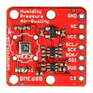
By using our website and services, you expressly agree to the placement of our performance, functionality and advertising cookies. It runs using a 3D-printed Terminator skull. dehipu has added a new log for Fluffbug. Did you find a solution? Already have an account? The output is clamped between -1 and +1. They simply report the current pressure over SPI or i2c, or as an analog voltage between 0 and 3.3V or 5V. There are also a bunch of different footprints for these sensors, but the most common one is an 8 pin DIP package. Since analogRead() values go from 0 to 1023, while analogWrite() values go from 0 to 255, we need to divide the potentiometer reading (potValue) by 4 before using it to set the regulator control signal. darkmoon3d liked Anableps Buoy, Invasive Species Alerts. Depends on what you want to do with it exactly. The first manifold was made by my university's machine shop. Whatever makes it easiest based on what you're connecting up and downstream of the regulators, really. We also create the variables flowReading and potValue to store the values that the Arduino reads from the flow sensor and potentiometer. Is this something that only needs a few pressures? This did work to some extent, and rapid pressure deflation is easy to achieve; however, fine control is not so easy. Connect an actuator and turn the potentiometer dial to control how much pressure it receives. The code is a work in progress; so far, I can read the pressure sensor value, compute a PID output and actuate the valves accordingly, and send & receive sensor values and PID parameters over USB. Idid have to smooth the analog setpoint measurement, as there was some noise in the signal. Built a Mini MIDI controller using an Arduino Pro Micro How to stop servo jiggling? based on your interests. The threaded hole on the left face will be plugged; it's just there to make it possible to drill the hole for the top barbed connector. If ones requirements cant be filled by that level of equipment and control, then its time to look at commercial regulators. Plus, I wanted to learn how to use a mill. Every component has its own specifications and can withstand different maximum pressures. Ialso had the campus machine shop make a manifold out of aluminium, which came out perfectly. Are you sure you want to remove yourself as There is also a jumper to supply either 3.3V or 5V to the sensor, specifically for the analog model. If you were able to get the guide's Blink example to work, you're ready to write and upload your own custom code to control the board hardware. I will be posting the code on github soon, along with a little demo of the regulator in action. I have worked with some commercial regulators (Bellofram units) on professional projects. Basic feedback control can be achieved by utilizing conditional statements with the sensor values.
The PCB should fit inside that, minus a couple millimeters on each side to allow space for an enclosure. Fascinating, reminds me of my oldie nucleonic ore flow days, pair of Cs137 beta into iron ore curtain horizontal pair of counters measuring mass flow circa 1980s Mt Newman mining. License: Creative Commons Attribution Share-alike (https://creativecommons.org/licenses/by-sa/4.0/legalcode), Proportional solenoid valve. Try closing the manual flow valve. The examplesand referencepages on the Arduino website are a good resource for discovering more things you can do with your code. My McGyvered solution was to set a threshold for opening the vent: if the output of the PID is below that threshold (arbitrarily set around -0.5), the vent valve is opened. I.e. It should also be as small as possible while still leaving space for the two valves, the pressure sensor, and a PCB which will house a microcontroller along with all the components and connectors needed to drive this thing. For me and my fusorwell, I had to create my own, actually fairly similar to this setup, but for far tinier amounts it doesnt take much gas to bring a 10 gallon or so tank up to about 1/100th of a millibar, and to regulate a lot finer than that far less than the initial fill. The vent valve can be only fully closed or fully open, and it vents quite a lot of air every time it is open, even for just a few milliseconds (it takes ~25ms to open it and close it). Definitely gonna lose some time exploring that supplier.Thanks for all of the resources! [Craig Watson] did exactly that, but found the results as disappointing as they were expensive. This makes it super easy to use, as there are just a few wires to connect; no amplifier to design, not much to troubleshoot, and nothing to calibrate. Ichose to go with a 3.3V operating voltage, for easier integration with other microcontrollers over i2c, since basically everything nowadays runs on 3.3V. For this we have two 4-channel Digital-to-Analog chips (MCP4728) that produce voltages from 0-5V as input for our air-pressure controllers. The behavior may be a little counter-intuitive since these solenoid valves are the "normally closed" model, which only open when they are powered. Contact Hackaday.io By using these variables, we don't have to update numbers throughout the code every time we change the wiring. Ulrich wrote a reply on LORA for BRESSER 5 in1 Weather Station (MAKE IOT). This will be a bit different in a real application, with other parts hooked up to the output (and it could even be solved simply by adding a pressure tank on the output), but I still want to improve the performance as much as possible now. They are imprecise (especially at low pressures), leak a lot of air, and have a tendency to report incorrect pressures. The code for controlling the regulator via the potentiometer is also inside this loop. In the Arduino Programming Platform, compile your code and upload it to the microcontroller. In concept, about the same thing. We also use them for PDMS valves that were introduced by Quake. This leaves little space for the components, so I had to pack everything in quite tightly and minimize the number of components on the board. And don't hesitate to ask if you have any more questions! Again, we use analogRead() to get a value from the flow sensor analog input pin, then scale this raw value to a reading in SLPM units using the calibration formula provided by the sensor manufacturer (read the datasheet for more details). To interface with a 5V microcontroller, one would need either a level shifter (for i2c), or a simple voltage divider for the analog set point. 06/01/2018 at 19:29, Adobe Portable Document Format - Once we have this value, we use Serial.print() to send this information to the computer, where it is displayed in the Serial Monitor. If we want to turn off the valve instead, we would use digitalWrite(valvePin, LOW). You can find the complete bill of materials linked in the article:https://www.sciencedirect.com/science/article/pii/S2468067218301147, Direct link to BOM: https://osf.io/byvmh/. This project is born out of necessity, as part of my microfluidics control system. Thanks for the suggestion! For the communication between the pressure regulator and external microcontrollers or computers, Iwanted an i2c interface as well as USB (which would be used both to control the regulator and to program it if necessary). I really enjoy your project !
A rotary encoder and LCD makes it easy to change the setpoint and view it and the measured pressure. On the software side, Imade use of the Arduino PID library. It must be possible to make it with a mill, maybe even just a drill press. Finally, I managed to produce our first open hardware project. Electrolytes, Theyre What Dehydrated Hackaday Writers Crave! For the regulator, we need a continuous control signal, unlike the valve which only requires a binary on/off signal. Learn more about the MPV used in this Microfluidics Controllerhere. The board can also control 8 air switching valves. Ideally, I'd like to model the system and take a smarter approach than just using an autotuner or trying a bunch of different parameters until it works well, but Idon't know if I'll have the time to do that. The flow sensor and potentiometer output analog voltages, so we connect them to the analog input pins A0 and A3, as seen in the wiring diagram in the assembly instructions. They will end up being a little under 50 x 50 x 50 mm^3, so stacking one on top of another would be useful at least in my application (where they will reside in a box ~130mm tall). Monitor the filters and status of an RO unit. For that project, I need precise air pressure levels, and a way to set them using a microcontroller. Project owner will be notified upon removal. How Does The James Webb Telescope Phone Home? We also added a barrel jack for the air pressure controller supply.
Since our DAC produces 0-5V it is important to chose the correct 0-5V command version. Pressure will often swing wildly around the setpoint for a second or two before stabilizing, and there is no good way to reliably get close to the setpoint with this setup. All it took was 5 or 6 hours of work (per piece), a few mistakes, and some cursing. In order to validate the concept, Ibought a pressure sensor and two solenoid valves (see bottom of this post for details). However, unlike setup(), this function repeats continuously, with the speed at which it repeats determined by the delay() function. Finally, we can also read and display sensor values here. For example, using digitalWrite(valvePin,!digitalRead(valvePin))instead ofdigitalWrite(valvePin,HIGH)will toggle the valve state on each loop so that you can get alternating actuation. First of all, Ihave to speed up the ADC. I had a similar need to control pressure in a vacuum tank (deuterium in a fusor), and pretty much all the commercial solutions would be fine for a big lab paying PhDs to sit around and do nothing while they waited speed is money for that crowd those sit-a-rounders arent cheap.
Sitemap 31