
The coefficients are real numbers in the range 0..2 so they are multiplied by 0x10000 and converted to integers. One group had a huge IBM-360 with 128kB but under 1MIPS. We can compare each of the examples with each template. Make sure you don't accidentally have any blank lines. How come a youngster knows an ancient language like BASIC (didn't know it's even still in use, thought it died quietly like a decade or two ago), but not C or Python? The LDA I used separated just two classes but, of course, I had 10 words. I suspect that won't work with the sort of project you'd use an Arduino for. It means that the lower frequencies of speech (below 1.4kHz) are de-emphasised. BASIC is not dead, my school used something almost the same as it for robotics. Alexa, Siri, etc. If the bands are far apart, you don't want Q so big there are gaps between them. A template is a typical example of an utterance. I just taped the whole MAX9814 module onto the boom of an old headset. An FIR filter requires more coefficients and more maths to get the same response curve as an IIR filter. Click on a cell in the grid to display the utterance; the horzontal axis is time and the vertical axis is the amplitude of each band. Answer It is available here. I used what I think is generally called a a "K nearest neighbours algorithm" but there are lots of others you could try. Something for _you_ to try out different ideas.How are you at programming and maths? Recompile those sketches so that they perform bandpass filtering on the Arduino. and I am mainly concerned about the byte size that the system can hold. The program calculates the mean and S.D. of the row of the grid is displayed.
The IEEE papers weren't reporting very good results for speech recognition (my Arduino system only works under ideal condition - it's pretty poor in the "real world". The list of utterances doesn't have to match the training set - you could add some "incorrect" words. Arduino Sinhala Tutorial 36 Talking Arduino Voice, HOW TO CONTROL LEDS BY VOICE USING ARDUINO AND BLUETOOTH MODULE, Basic4Android (B4A) | How to Control LED Using Voice Recognition with Arduino and Basic4Android, Arduino Tutorial Arduino control with Android voice command via Bluetooth, How to make a voice recording greeting card with Arduino || In Telugu, Voice Controlled Robot using Arduino DIY Project Full Tutorial, How to Talk with Arduino Board | Voice Recognition Module | Record your Voice. SpeechRecog1.exe calculates the templates whch will recognise those utterances. Firstly use SpeechRecog1.exe to calculate the coefficients for the digital filters as described in Step 6. The Arduino sends sample utterances to a PC and the PC calculates the utterance templates. 1 year ago, Thanks.It's an old book I happen to have in my bookcase. the second formant is 600Hz to 2500Hz. The Arduino divides the whole utterance into "segments" each 50mS long (in some of the literature, they're called "frames"). Because this system is for recognising a single speaker's voice, it should be tuned to that speaker. The speechrecog2.ino sketch uses the templates to recognise utterances. For a start you need a microphone and amplifier module, readily available for near nothing. I tried shifting and stretching the whole utterance and I tried shifting, stretching and moving the centre part around. I doubt if it would be plug-and-play for the form design files (*.DFM - I've not tried it).

Let's say we want a sample rate of 8000sps, that's 125uS per sample. Do you know how well Siri, Alexa, and the others work? It's not a difficult algorithm.Peter. Women's formants are 15% higher and children around 35% higher. A Nano has only 2k bytes of RAM so we can't store all the samples of the utterance and analyse them slowly. I am underage, and I wouldn't drink. It's easier to get the maths wrong for an IIR filter so that he output goes crazy or gets stuck. The utterance is assumed to start when a the total energy in the bands exceeds a threshold. Which template is most like that example? How does a Nano compare with back then? You might have to write your own trainer on a PC but you have all the data you need from the Arduino. A formant is a peak in the energy of the spectrum and a vowel is recognised by the relative sizes and frequencies of the first two or three formants. DrDiettrich: The Arduino library has put the ADC into single conversion mode so we need to set ADSC to start each conversion. So I went back to the absolutely simplest scheme. You could add the Talkie library to provide feedback of the word that has been recognised. It's straightforward to get formant tracking working when you've got a complete spectrum from a Fourier transform or if you use LPC but it simply doesn't work with the 4 frequency bands we've got. Clearly, a Nano isn't going to be as good as those. (Not the file itself, to be clear, but title and authors of the paper), Reply This suggests to me that speech recognition should be the task of a separate specialized controller module, added to the Arduino. I've used it - it's a nice system.

Optionally, SpeechRecog1.exe collects more utterances for testing. The voltage from the amplifier will be centered around 512. For our signal processing, we want it centred around 0. The SpeechRecog1.exe Windows program calculates digital filter coefficients. You should use a little hysteresis which calculating ZCR so as not to pick up low-level noise.
arduino If the output also depends only on previous output values then it is an Infinite Impulse Response filter: "IIR". Or do you have a shortlist of such modules already? To me, that makes sense. If Instructables hasn't mangled them they should be good enough for OCR. And also thank you for putting the code from your other instructables out there, too. I'll be happy to andswer any questions.I think of this instructable as an experimental project. By calling analogRead() once, we get the Arduino library to set up the ADC. The amplitude of each band in each segment is measured.


The first male formant frequency varies between 250Hz and 850Hz. The microphone should be to one side of your mouth to avoid "popping" with plosives (p, t k) or other breath noises.
module By re-arranging the equations we can calculate the filter as: You can see typical filter responses in the spectrum above. So you might stretch the first half. > const int AUDIO_IN = A7;> Should I change itYes. In hardware section you've connected Vdd & Gain to A3 but in the ino files you've written const int AUDIO_IN = A7;Should I change it or is it ok?And second, can you please say how you connected the MAX9814 to a microphone boom? The overall software system is slightly complicated. Within each segment it measures the amplitude of each of the 5 bands.The utterance is assumed to have 13 segments so that's a total of 65 16-bit ints covering 0.65 sec. Hi Peter,A bit late to reply, sorry about that. 1 year ago We want, say, four bandpass filters.
arduino microphone recognition module voice The Gain is connected to VDD which is the lowest gain. I tried it but it really didn't do a good job of distinguishing one kind of utterance from another. That's a work-alike freeware version of Delphi4. The sketch can send the values to the PC over the serial line but serial transmission slows it down to around 1100sps (at 57600baud). Heller, I was wondering what the best voice recognition system for the arduino was, I plan on having a robot that has the system built in (not an app on your phone!) A Nano has 2KB RAM, 32KB program ROM and runs at about 10 MIPS (depending on the instruction mix). The result is a 16-bit int centred on 0. I think the starting point for any speech recognition is going to be the bands and segments I've described. A single word is so short that Dynamic Time Warping is not useful. Each templates contains 65 int values and each value is compared with the corresponding one of the incoming utterance. Powered by Discourse, best viewed with JavaScript enabled. Did you make this project? The following Steps describe each of those parts in more detail.
Thanks a lot. In C we would calculate it as: where x[n] is an input sample value and y[n] is an output value. It deserves to be made into a scientific paper!Could you share the references you were reading? If you want to have fun and learn, why don't you start immediately?

Just forget about doing it with an Arduino. From now on, I treat the 5 bands equally. Do you believe that there might be some guidance available on the Instructable as time goes by? If you're a C programmer then it might be hard to translate.If you want to run it on a Raspi then you could try Lazarus. You could connect the module directly to one of the ADC input pins but in the diagram above I have included a simple RC high-pass filter. Wouldn't I be able to try to record 2 copies of speech, one normal and one with distortion? Or what about a remote-control robot? The coefficients for a bandpass biquad filter are. Arduino Robotic Arm Controlled by Touch Interface. Hi Peter,Thanks for your awesome instructable - not only a very interesting topicbut also extremely well explained and described.Would you consider putting your sources on github? And it can shift in fractions of a segment so a shift of 0.3 means the new value is 70% of the current value plus 30% of the adjacent value. You already have that.Is there anything you need to know? My dad showed me his old TRS 80 computer and told me about how he still had some old cassettes, so I started learning how it worked.
v3 The 10-bit result of the ADC conversion is read by reading the 8-bit ADCL register then the ADCH resgister.
voice module recognition microphone arduino The utterances are presented in random order. Introduction to voice recognition with elechouse v3 and arduino. download on the web.Let me know whether you manage to compile it.All the best, Peter, Question The circuit I used is shown above. When you read ADCL, the value in ADCH is frozen until you read it too.
recognition epikelectronics That's particularly true when you're using integer arithmetic as we'll be doing on the Nano. I used an LM358. (You can edit the numbers in the Memo in SpeechRecog1.exe and it will plot the results. . Copy the Coeffs.h file into the same directory as the speechrecog1.ino and speechrecog2.ino sketches. Especially for a re-implementation. Any module that has external memory would be good. The program has stored the previous 2 input values and the previous 2 output values. I totally get your concern about having to support old code.
easyvr So I reckon we're stuck with using a few digital filters. Perhaps you can think of other ways of classifying the bands and segments. 2 segments.
recognition arduino compatible module voice v3 kit I have ordered the appropriate input, the MAX 9814 and I will be ready to go when it arrives.
continually listen for a "wake word". If you want to have fun and learn, why don't you start immediately? I don't need Siri or Alexa (although I would like to try using an Raspberry Pi for that. SpeechRecog1.exe makes the band filters "equally spaced" on a logarithmic scale. Or you might stretch the whole thing and shift it slightly to the left.
Time is divided into 50mS segments.
arduino recognition voice using speech module library uno vr The speechrecog2.ino sketch (download: step 10) is compiled using the Templates.h file and the Coeffs.h file. If you search Instructables for "Alexa" or "Siri", you'll find around 200 projects - many of them could benefit from not requiring an internet connection. I allow the whole utterance to shift by up to (e.g.) The results are not quite as good but should be over 90% correct. The 3.3V output produced by the Nano is fairly noisy so needs DC4 and DC6 as decoupling capacitors. Can it do anything useful at all?

I used the 3.3V output of the Nano as the analogue reference voltage so 0 to 1023 means 0V to 3.3V. A fixed number of segments (currently 13) constitute an "utterance". for all the utterances). I found something under Q=2 is about right. . is re-calculated for each template.

Formant tracking watches how the frequencies of those peaks change during the utterance. The Q factor should be the same for all bands which implies they have to be equally spaced on a logarithmic scale. That's a work-alike freeware version of Delphi4. I don't mind making all my Windows code public but I don't want to have to support it. Neither worked well for me. The PC displays the result in the grid. https://www.facebook.com/groups/virtualbeings/permalink/1450290178769526/, #virtualbeings : Official LINE PLAY | Official Site https://www.facebook.com/groups/virtualbeings/permalink/1450291798769364/, #virtualbeings : [] CFO ", " https://www.facebook.com/groups/virtualbeings/permalink/1450282855436925/, #chatbotsindia : Kyra, India's 1st virtual influencer is here from the Metaverse: Himanshu Goel & George Tharian | OMG! 8-bit addition takes 0.4 to 0.9 uS. as in making something that understands "Hey robot, hoof it on down the road 12 whatevers". Then use SpeechRecog1.exe to stored some training and test utterances as described in Step 9. How? In the main loop, to start a conversion we set the ADSC bit (ADC Start Conversion). 16-bit addition or multiplication takes around twice that (as you'd expect).

the amplitude. I think I could use the EasyVR Shield, but it only holds 32 triggers.
The A/R pin controls the "Attack and Release Ratio" of the automatic gain control: The actual timing of the attack and release is set by a capacitor on the module. Click the "Templates" tab then the "Train Templates" tab to view some utterances with which to calculate the templates. each [seg,band] for each template (row of the grid). Multilayer neural nets can recognise patterns that are not linearly separable but, in my limited experience, require huge amounts of training data. Because the module is AC-coupled, two resistors are used to centre the ADC input around 1.65V. The speechrecog2.ino sketch sends the text of the recognised word to the PC over the serial line but you would use it in you project to control something.
module voice recognition arduino I've uploaded the Delphi4 source to the Github repository.I believe Delphi4 is available for (unofficial?) But an IIR filter is less stable. Most people seemed to be pretty pleased just to have made some recordings, done a Fourier transform and drawn some graphs. Let's assume the utterances we're trying to recognise are the digits "zero" to "nine.

(A Nano can just manage to calculate Fourier transforms but not quickly enough.). That smoothed 5V is filtered even further by R1, DC1, DC2 and acts as a bias supply for the microphone through R2. An Arduino with an ATmega328 is not fast enough to do that as the sound arrives and not big enough to hold the samples of a complete utterance for later analysis. You can have nearly as much fun making something that understands "LED", "ON", MOVE", "ONE", TWO", "THREE", etc. You want a recognition algorithm that (once it's been trained) can be run on an Arduino. It would be great if you worked on it further. As a result, we're limited to maybe a dozen arithmetc operations per sample. I'll call them "bands" even though ZCR is not really a frequency band. On the PC, SpeechRecog1.exe calculates the templates whch will recognise those utterances. If the values for a (t,seg,band) vary a lot for that class of utterance, the template's value is less important than if the values are always pretty much the same. However, shifting an utterance to the left or right can produce more good matches without producing more bad matches. If you select several cells, they will all be displayed so you can compare them.
electronicscomp I have a friend who has messed with Linux before, and he agreed that SOPARE is a good system. With a good training set, it's usually 100% right. For a bandpass filter, Q= fcenter/ (fmax - fmin). As in, the Very Very Very Hard part if you dont use pre-recorded messages from the same voice.

A "three" often looked like a "seven" and a "four" looked like a "zero". It basically identifies the words and then checks the order to see what the response should be. I would be using an UNO. How would you like to be able to proceed? The Gain pin controls the gain of the AGC: In the circuit shown above, I have left A/R unconnected. You could connect them to digital pins of the Arduino so you can control them in software: for "unconnected", set the pin to input. That will load some utterances with which to test the templates. I found a gain of 40dB gave the best signal-to-noise ratio with the microphone on a boom near my mouth.
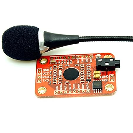
We can ignore a1 as it is zero. Once the 13 segments have been stored, we have to choose which of our sample words we think those 65 numbers most resembles. We would prefer to be doing other things while the ADC is waiting for the conversion so I do it differently. An "IIR" is a "recursive filter".). 6 months ago. Is That Real? The templates are exported as the Templates.h file. 2 GB is a huge amount of data to work through for a 16 MHz, 2 kB RAM processor - even when disregarding the voice recording part. Because it has stored 2 of each values it is known as a second order filter. Do you mean write your own Windows code? In the image above, the frequency axis (x-axis) is linear. This looks to be an exciting learning opportunity. Awesome. The band amplitude values are compared with the template values. The red band is the ZCR. If you Open the COM port and talk into the microphone, the utterance will be displayed. Those are built by a large team of specialised engineers, have a supercomputer to help out, and are still prone to errors. Thanks for sharing! There are lots of free neural net training programs available in, for instance, python or R. Maybe there is some way of using a genetic algorithm to make a classifier. We also have to collect the data from the ADC, calculate the amplitude of the bands and store the results in an array. If the system shall recognize multiple speakers, add enough memory for each one. With only 4 frequency bands, we can't hope to calculate formant frequencies but they will affect the energy in the different bands. So I was still using the module's own microphone.Please let me know how you get on. So the first stage is to pass the input through different bandpass filters. The ADIF bit (ADC Interrupt Flag) is set once a conversion is complete. What is (objectively) the best voice recognition system for the arduino.

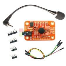
I was desperate for something to read during lockdown and found in my bookcase an IEEE report on Speech Recognition from the late 1970s. I will need to find a way for an arduino and a Raspberry Pi to communicate. An utterance starts when the amplitude exceeds a threshold. A MAX9814 includes a microphone amplifier and an AGC (Automatic Gain Control). Click the "Train Templates" tab to record a training set. This tells ADC to start the conversion. I think you'd be better starting from scratch in your favourite language. When you have got a set of templates that you're happy with, you can export them to the Arduino as the Templates.h file.
recognition robu That's what I'm going to attempt. x[n-1], y[n-2], etc.
Nowadays, people might use formant tracking.
Sitemap 2