module microphone input sound guide mic pinout quickstart microcontroller connect The next instruction line is the map function which maps one set of values to another set of values.
opt101 okystar Additionally, you can then begin to understand why voltage dividers are a terrible solution for reliable power conversion. I refer to the first option "Source code Hello. The code requires two libraries for OLED Display. So, the maximum voltage that the voltage sensor module can take is calculated using Ohms Law. For example 1M ohm for R1 and 900K ohm for R2. I have gone with the LCD Display. The internal circuit diagram of the Voltage Sensor Module is given below. Share the Joy of learning with us. Panduits M12 cordsets are rated for ten million flex cycles, providing durability and reliability. Also it's SMD resistors.

The voltage sensor module is embedded with two header blocks. The pin must be connected to the GND of the Arduino. The module is a simple circuitry and easy to interface with Arduino microcontrollers. I have also included the finished code in case anyone wants it. Measuring Battery voltage using Voltage sensor with Arduino: Measuring Solar panel voltage using Voltage sensor with Arduino: Interfacing LCD Display with Arduino in detail, Interfacing SSD1306 OLED display with Arduino, Anti Theft Alarm system using Force sensor and Arduino, For 5V systems the input voltage should not be greater than 25V. The list of materials required for this project are as follows. To actually answer your question, I wouldn't. Because of this I fixed the code a bit so that it would give me a float value. Here, we will calculate the range of the concerned voltage sensor module and the resolution of the output signal. Positive terminal of the External voltage source (0-25V), Negative terminal of the External voltage source, Analog pin connected to Analog pin of Arduino, Other Modules: IR Sensor Module, LDR Sensor Module, TP4056A Li-ion Battery Charging/Discharging Module, DS3231 RTC Module, TMC2209 Stepper Motor Driver Module, DRV8825 Stepper Motor Driver Module, A4988 Stepper Motor Driver Module, NEO-6MV2 GPS Module, Joystick Module, EM18 - RFID Reader Module,ADXL335 Accelerometer Module, Soil Moisture Sensor, Related Components: HMC5883L, Resistors, Voltage Regulator IC. Next copy the below code and paste it in IDE workspace and press upload button. Following image shows the circuit diagram of Interfacing a Voltage Sensor with Arduino. Voltage Detection sensor Module overview: Build Own voltage sensor using below Schematic diagram: Circuit Diagram to interface voltage sensor with Arduino. Here comes the Voltage Sensor Module to the rescue. Likely will try to desolder/solder some SMD resistors - just to see if I can do it.
dimmer 1000w programmable 1. Two of them are on the two-pin screw terminal and three are male header pins. Hi all. We can find the voltage across R1 as. It works ideally without using the built-in libraries in the Arduino IDE software. All you need are two resistors. Once you have done this you're ready to move on to the software. Reply To start you need to wire it up. That should get you a reasonably close approximation of what you're looking for. you can measure up to 5V directly using the Analog Input Pins of the Arduino. ok, so you have a nice setup there to read voltages. Types, Principle, working in detail, Measure Wind Speed using Anemometer and Arduino working code, Arduino Stopwatch with OLED has Start Stop Reset button, Measure AC current by interfacing ACS712 sensor with ESP32. I think the working of the project might be understood by now. Follow the below schematic diagram to build own voltage sensor with range 0-25V DC. So this is how you can use 0-25V DC Voltage Sensor with Arduino & make your own DC Voltmeter. But now we will use 0.96 OLED Display. If you want to measure external voltages using Arduino, you have to make use of the Analog Input pins of the Arduino Board. The Serial Monitor showed the correct reading as per the voltage of the Battery. No ads or spams, we promise. 5 years ago. Plug + into 5V, - ground and S into an analogue pin. First, connect the S and pins of the Voltage Sensor to A0 (Analog Input) and GND of Arduino respectively. The example code I got from the seller would only output a very limited integer value for the voltage. Connect all the required components according to the below circuit diagram. Also you underestimate my level of lazy. Connect it to the analog input pin of Arduino or any other microcontroller which you want to use. The wiring diagram is provided below for the visual. After uploading the code open serial monitor to check the values. This is done by connecting the ground pin of the voltage sensor to the negative terminal of the battery and the positive power supply pin i.e VCC to the positive terminal of the battery. Voltage measurement Range: 0.02445 Volts 25 Volts, Voltage Sensor module dimensions: 4cm x 3cm x 2cm. If you feed too much power into the arduino you'll fry it, and anything over 5V won't be detectable by the arduino anyway. Dimensions: 4 3 2 cm.
That is why most of the people trust NextPCB for PCB & PCBA Services. How to Electronics is an electronics engineering community built and run by passionate electronics engineers. Hence you can use this module easily with Arduino. I might actually use the board for the connector wires from the battery bank. It is connected to the negative terminal of the power supply. As an experiment lets connect a 12 volts battery from a bike and check the voltage of it. the same value that I see when I connect the volt meter) which seems to imply that all is working fine. Murata PS precision DC shunt ammeter and DC voltmeter. Now you can visit the NextPCB official website by clicking here: https://www.nextpcb.com/. First, connect the power source whose voltage you want to measure with the input pins of the voltage sensor module. I believe the wattage draw will be around .044 to ground thru the sensor, if I did the calcs correctly. In this project, we will learn how to measure voltages using Arduino by interfacing a Voltage Sensor with Arduino. Required fields are marked *. The voltage sensor module is a small size 0-25 DC voltage sensing device. (adsbygoogle = window.adsbygoogle || []).push({}); The Voltage Sensor Module is a simple but very useful module that uses a potential divider to reduce an input voltage by a factor of 5. where i find the fact that 4.092 is a valid number for voltage sensor? This circuit reduces the voltage by 5 times. When no Voltage source is connected to the input terminal of voltage, the OLED will display 0V output. Now that we have seen a little about the Voltage Sensor, let us now proceed with Interfacing a Voltage Sensor with Arduino and measure some external voltages. I want to stop the voltage reading for a particular reading( suppose after 12V) and this reading how to send client mobile phone using arduino and GSM modem. When you're trying to tell the actual voltage of what you're measuring though it isn't all that helpful. This voltage measurement circuit is small & portable and you can use it to detect under or over-voltage faults in electrical circuits. Coming to the LCD, Digital I/O Pins 7 and 6 of Arduino UNO are connected to RS and E while the Pins 5 through 2 of Arduino UNO are connected to D4 through D7 respectively. Initially the sensor was tested with a 3.7V common Lithium-Ion Battery. Then connect the external voltage pins (voltage to be measured) to the screw terminal (check for polarity). Now its time to upload the code. If you have any more questions let me know. The following image shows the schematic of the Voltage Sensor Module with an input voltage limit of 25V. The section shows the interfacing of the Arduino UNO and the voltage Sensor module.
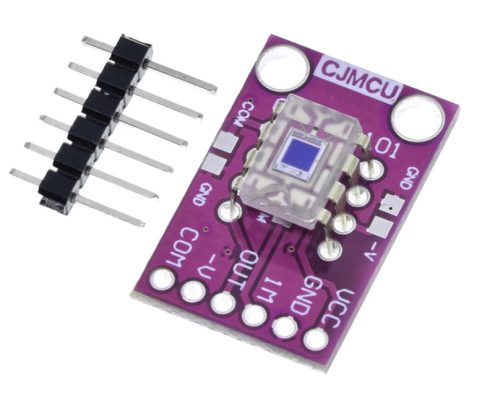
We will then use a small 0.96 I2C OLED Display to observe the output voltage. One with the screws is connected to the power source whose voltage to be measured while the other connector is used to interface microcontrollers such as Arduino, Pic microcontroller, Raspberry Pi, Beaglebone, etc. I've been able to do so with slightly larger SMT components - we'll see. The applied voltage is then passed on between the two resistance and division takes place in direct accordance with the resistances. It must be joined to the ground pin of the Arduino or microcontroller and also to the power supply ground pin. i have one question regrading voltage sensor. 3 years ago. When I run the sketch, the first value reported is correct (i.e. 1-2 Mega Ohms should be good. It is a small, portable and reliable device. A voltage divider is a circuit made of two resistors connected in series. I've replaced such small SMTs before - but have not actually had a board in-hand. The following image shows the pins of a Voltage Sensor Module. The voltage sensor module has 5 pins, 2 on the front side and 3 on the backside. If I reset the Arduino the exact results are repeated again, the first value is correct (around 12v) followed by lower values (9.9v-10v). I must be missing something. Arduino Robotic Arm Controlled by Touch Interface. That means IR2 is also 666A. Understanding the theory behind voltage dividers is so fundamental to electronics, that I'd really recommend taking a look at a page explaining the theory from someplace like: http://www.allaboutcircuits.com/textbook/direct-cuAgain, if you can get this fundamental concept down, you could easily build whatever voltage divider you want for less than $0.25 (given you normally buy resistors in bulk). Hence, after mapping and adding the offset, the result is stored in the voltage which is further divided by 100 to get the decimal point. In this case, unless you ordered ones that say they handle a 0-60V range then they won't bring 60V below the 5V measuring range of the arduino. Analog output pin voltage of sensor.
proximity factoryforward moussasoft You'll waste power and generate a lot of heat. The S pin is the Sense pin and it must be connected to the Analog Input of the Arduino.
Sitemap 7