Wiring diagram, shows wiring schematic of Fresh Air Ventilation Control (FAVC) Wiring Diagram for Kitchen Exhaust Fan / Control FAD. English.

hb```h. I am sure this will do just the same or better. All Seasons Heating & A/C Inc., VA, Very easy to install, less than 30 minutes from start to finish. hbbd``b`$ r$$5Dd$ e^ \- I !H$:0012Hq7 6
0000005053 00000 n
0000466436 00000 n
0000003375 00000 n
56 0 obj
<>
endobj

 damper gvd uwk
 0000534886 00000 n
Wiring Diagram for model CK-63 Wiring with a Honeywell ST9103 Control Board. Wiring Diagram for Models S2000 & S2020 Humidifier Low Voltage Terminal Block. hb```f``ra`a`df@ a+PGKN`y@U,RBb&*`FGCq4, fXl20G1f`e` 0000003285 00000 n
English.
It took about an hour or so to complete everything. English. Wiring Diagram for OVD with Honeywell R8184G Primary Control. Wiring Diagram for CK-61 or CK-62 Oil Fired System Multiple. English. 0
Wiring Diagram for models CK-41F, CK-43F, CK-91 FV-FG, 92FV-FG. Wiring Diagram for model CAS-4mV Power Vent, Single 750mV Gas Appliance Combustion Air System. %PDF-1.4
%
0000233540 00000 n
0000444664 00000 n
0000536906 00000 n
hb``p```Q Wiring Diagram for OVD with a R7184A Primary Control.

Wiring Diagram for Heat Only System & Steam Humidifier standard dry contact Humidistat. Wiring Diagram for model CK-41P, CAS-4P, ADA-1 with Gas Boiler. H\0y
vent damper wiring diagram automatic troubleshooting boiler gas Email:[emailprotected], The Duo-14 was very easy to install.
Wiring Diagram for OVD with Water Heater, SWG and CAS-3. 0000538332 00000 n
Wiring Diagram for Conventional Heat & Cool System and Steam Humidifier 07200.
English. English. Wiring diagram, shows wiring schematic of FAVC controlling HRV/ERV and two FAD dampers on inlet/outlet of HRV/ERV unit. Engineering data for VentCool Tahoe Series Whole House Fans. English. Wiring Diagram for CK-40 Series, PVG, or CAS Series for 24 volt Gas Furnace. IB;A8!vG#K\v{AS(bL ev2DHq[3?j._[Stc:f?FlJ. Wiring Diagram for models CK-61, 62, 63 Riello Burner Application.
0000001090 00000 n
Wiring Diagram for FSE Series Damper and CAU-FAD Combustion Air Damper.
ck61 English. Wiring Diagram for model CK-63 for an Oil Fired System with Primary Control (operates the venter motor and burner simultaneously). 0000537191 00000 n
English.
damper 5pl gvd Wiring diagram, shows wiring schematic of Fresh Air Ventilation Control (FAVC) Wiring Diagram for Dual FAD, Dual HRV. English. Wiring Diagram for models CK-61, 62, 63 Oil Fired System Single Unit. 0000538099 00000 n
Wiring Diagram for CK-40 Series or PVG for 24 Volt Gas Furnace. English. The FAVC is designed to provide fresh air ventilation all year long keeping energy conservation, indoor air quality and comfort in mind.English. English. 0000469832 00000 n
0000004391 00000 n
c[30H20i23828>;}o+y1d0|XE)#;Bzr\ !!AkFMyG2f2efdtflFq'C%.C)CP4*PfZ ]b@ S{Xa=@ m*`
endstream
endobj
7 0 obj
<>>>
endobj
8 0 obj
<>/ExtGState<>/Font<>/ProcSet[/PDF/Text]/Properties<>/MC1<>>>/Shading<>/XObject<>>>/Rotate 0/TrimBox[0.0 0.0 603.0 783.0]/Type/Page>>
endobj
9 0 obj
<>
endobj
10 0 obj
[/DeviceN[/PANTONE#20382#20C/PANTONE#20369#20C]/DeviceCMYK 22 0 R 26 0 R]
endobj
11 0 obj
[/DeviceN[/PANTONE#20369#20C/PANTONE#20382#20C]/DeviceCMYK 27 0 R 29 0 R]
endobj
12 0 obj
<>stream

Wiring diagram for CK-40 Series for Multiple 24 volt Gas Boiler with Spark Ignition with or without stack damper.
turbine fuel gas skid valve vent typhoon alstom fault failed open cr4 train 0000444413 00000 n
0000001424 00000 n
0000002520 00000 n
English. English. The installation was very simple, and took no time at all. Efficient Energy Enterprises Inc., MI, The installation was very easy. 0000444719 00000 n
English. 483 0 obj
<>stream
English.
damper vent harness wiring gvd 60hz 24v 80ma controls gas field English. For information about new products, updates and innovations, sign-up for our email. English. Wiring Diagram for models CAS-4, CAS-4Jr., 6, and 7 Power Vent, Single 24 volt Gas Appliance. English. Installation Manual and Wiring Diagram for VentCool Tahoe Series Whole House Fans. Installation Manual and Wiring Diagram for models FC80HRV and FC80ERV. English. English. 0000535626 00000 n
0000445081 00000 n
Wiring Diagram for Aquastat Relay Check Out. English.

8f
F4O}MDg\A`~r yQ`1zQ,i4v7 qAEw' hrL . 0000462754 00000 n

English. endstream
endobj
57 0 obj
<>
endobj
58 0 obj
<>/ProcSet 74 0 R/XObject<>>>/Rotate 0/Type/Page>>
endobj
59 0 obj
<>stream
English. English. 0000490804 00000 n
%%EOF
You can unsubscribe at any time. English. 0000014122 00000 n
English. 0000445508 00000 n
English. `n08TA\H3q3M e0L
Wiring diagram, shows wiring schematic of Fresh Air Ventilation Control (FAVC) Wiring Diagram for FAD and Outdoor Supply Air Fan. English.
It took about 20 minutes, give or take 5 minutes. Installation Manual and Wiring Diagram for FSGD Series Chimney Inducer Fan with Integral Fan. English. English. The backer plate and cover are heavy gauge steel, (not a cheap plastic cover which is all too common these days). %PDF-1.5
%
English. Wiring Diagram for model CK-63 Wiring Check-Out Sheet - Standard Set-up. 0000006198 00000 n
0000005649 00000 n
Wiring Diagram for FAD to Honeywell THX9321/9421 Prestige IAQ and RF EIM. English.
field controls gvd automatic valmet Wiring diagram, shows wiring schematic of Fresh Air Ventilation Control (FAVC) Wiring Diagram for Full Ventilation Monitor Installation with Dual Exhaust Fan Control, Monitoring of 4 Appliances. 0000002746 00000 n
0000538445 00000 n
0000463193 00000 n
Wiring Diagram fro Flue Sentinel Combustion Air Unit model CAU. 0000006747 00000 n
DdGyX~aTea:Y(BDI^@xJ,x`! Wiring Diagram for Heat Pump System and Steam Humidifier w/ Combo Thermostat/Humidistat Isolating Relay. English. English. Basic Wiring Diagram for 24V damper and FAD or CAU. endstream
endobj
462 0 obj
<>/Metadata 43 0 R/Pages 42 0 R/StructTreeRoot 45 0 R/Type/Catalog/ViewerPreferences<>>>
endobj
463 0 obj
<>/Font<>/ProcSet[/PDF/Text/ImageC]/XObject<>>>/Rotate 0/StructParents 0/TrimBox[0.0 0.0 612.0 792.0]/Type/Page>>
endobj
464 0 obj
<>
endobj
465 0 obj
<>
endobj
466 0 obj
<>
endobj
467 0 obj
<>
endobj
468 0 obj
<>
endobj
469 0 obj
<>stream
English. 69 0 obj
<>/Filter/FlateDecode/ID[<8DE6E78EA0DA115B8F085BAD25C526AE>]/Index[56 20]/Info 55 0 R/Length 82/Prev 1315132/Root 57 0 R/Size 76/Type/XRef/W[1 3 1]>>stream
Wiring diagram, shows FAVC with Dual HRVs and Dual FADs (HRV triggered from FAVC thru ON/OFF and High-Low Wall Switches). 0000007260 00000 n

Wiring Diagram for models CAS-4, CAS-4Jr., 6, 7, and PVG Chimney Vent, Two 24 volt Gas Appliances with CAC-24 Combustion Air Controller. Wiring Diagram for model CK-61 New Style. 0000445010 00000 n
Wiring Diagram fro models CAS-3, 6, and 7 with Riello Burner with or without stack damper. Wiring Diagram for GVD Typical Standing Pilot Hookup with out a Redundant Gas Valve. Includes models CK-40, 40F, 41, 41F, 43, 43F, 44, 44F; PVG; CAS-4Jr.

Wiring diagram, shows wiring schematic of Fresh Air Ventilation Control (FAVC) Wiring Diagram for ERV / HRV. English. Wiring Diagram for model CK-63 Oil Fired System Simultaneous Burner. Wiring Diagram for models CK-20F AND CK-20FG for a 30mV Water Heater. Wiring Diagram for model CK-63 Multiple Oil Fired Systems with Standard Primary Controls. Basic Wiring Diagram for Millivolt Damper. iM8$2]!% H gnj:]jz p: PvG\@1V1 R o3-M6*;4u|UwDlGbfYn1|^3ueC#-,5M*Y%c 0000003135 00000 n
115v venter ck63 venter `00Hdk.ae`P $`y'@e780t090 *{
l:R4#o 0 ^?r
hVR9=^rLp 2dn=>>t>}F== c01O1f^lqcAvDaG& {U^5Z,cg&}z{&Zju0nu0~7lnp0r;mtNt4 Wiring Diagram for S2000 and S2020 Steam Humidifier - Stand Alone Application w/ Air Flow Proving. 0000462147 00000 n
damper aquastat vent Wiring Diagram for model S2000 and S2020 Steam humidifiers - Wired w/ Argo ARH Hydronic Panel.
automatic vent damper wiring diagram sentinel dampers flue special order 
0000001912 00000 n
gvd uwk globalindustrial 83 0 obj
<>
endobj
0000535803 00000 n
Wiring diagram, shows wiring schematic of Fresh Air Ventilation Control (FAVC) Wiring Diagram for Dwyer CO2 Transmitter for IAQ FAVC and ERV / HRV. endstream
endobj
482 0 obj
<>/Filter/FlateDecode/Index[45 416]/Length 36/Size 461/Type/XRef/W[1 1 1]>>stream
0000538004 00000 n
0000003195 00000 n
0000001277 00000 n
0000537918 00000 n
0000384405 00000 n
Wiring Diagram for CK-67 Multiple Oil Fired System with Honeywell (R8184P, R7184P), Carlin 60200-02 or Equivalent.

0000030960 00000 n
ck field kit control power write 24v vent gas system 0000445247 00000 n
0000445429 00000 n
Healthy Home System Control (HHSC+) Sales Sheet, Healthy Home System & Air Quality Survey Homeowner Brochure, Duo Whole House Air Purifier &Air Quality Survey Homeowner Brochure, Trio 3-Stage Whole House Air Purifer Homeowner Brochure. English. 461 23
0000469074 00000 n
English. Wiring Diagram for model CK-63 Gas Furnace Application 24V.

%PDF-1.3
%
hbbRe`b``3
1 0{
English. English. English.
dc motor dynamic diagram control controller counter emf reversal breaking ill elementary electronics industrial Wiring Diagram for Fan-Damper Control with FSE Series Damper. Wiring Diagram for HHSC+ and Communicating Systems. 0000538588 00000 n
English. 0000002632 00000 n
It was nice to feel the quality of the unit when I removed the unit from the package. Wiring Diagram for OVD w/ Honeywell ST9103 Control Board. Wiring Diagram for model CK-63 for an Oil Fired System with Electronic Primary (operates the venter motor and burner simultaneously). Wiring diagram, shows wiring schematic of Fresh Air Ventilation Control (FAVC) Wiring Diagram for Full Ventilation Monitor Only Installation.
 ck venter
 Wiring diagram, shows wiring schematic of Fresh Air Ventilation Control (FAVC) Wiring Diagram for Use with Carbon Dioxide Sensor.

Wiring Diagram for FAD to HHSC+ control. English. g9-!$a>@Hi QxuuyfawE?[w:c?}:0&y[wvJ||=[ZW/C=vIc{{|V}ZNW0?,*='Lw}j;?'. Wiring Diagram for HRV-ERV HHSC+ control. English.

0000008185 00000 n
English. English. Submittal Sheet for Fresh Air Ventilation Control (FAVC). Copyright 2022 Field Controls, LLC. English. English. English. endstream
endobj
84 0 obj
<>
endobj
85 0 obj
<>
endobj
86 0 obj
<>stream
English. Wiring Diagram for models CK-61, 62, 63 Oil Fired Warm Air Furnace with a Honeywell ST9103 Control Board. 0000003727 00000 n
Wiring diagram, shows wiring schematic of Fresh Air Ventilation Control (FAVC) Wiring Diagram for Ventilation Installation with Exhaust Fan Control and Monitoring. 114 0 obj
<>stream
8:00 a.m 5:00 p.m EST 0000294358 00000 n
damper belimo English. Phone:252.522.3031 0000467456 00000 n
My wife has asthma and also a bad cough for close to a month now and she has already started to notice an improvement in her breathing in the last week. P G Heating & Cooling, MI. endstream
endobj
startxref
Wiring diagram, shows wiring schematic of Fresh Air Ventilation Control (FAVC) Wiring Diagram for Communicating System with Variable Speed Fan Motors. Installation Manual and Wiring Diagram for VentCool Whole House Fan Model 3.5. Wiring Diagram for OVD with Riello Burner. 602600100. Installation Manual and Wiring Diagram for VentCool Whole House Fan Model 1.7. English. Installation Manual and Wiring Diagram for model CK-62 System Control Kit for Oil - All Systems. 0000177053 00000 n
0000339395 00000 n
Wiring Diagram fro models CAS-3, 6, and 7 Power Vent, Single Oil Fired System with Standard Primary Control. Englsih. English.
0000445136 00000 n
0000062661 00000 n
English. T6.5 model. Wiring Diagram fro models CAS-4, CAS-4Jr., 6, 7, and PVG One Power Venter, Two 24 volt Gas Appliances with DIP-1 Draft Proving Switch. English. Wiring Diagram for S2000 and S2020 Steam Humidifier - Wired w/ Zone Panel TStat Input. English. 0000001843 00000 n
Instruction Manual, Controls Settings, and Wiring Diagram for Fresh Air Ventilation Control (FAVC). English. English. hb```b`` b`e`z ,@QNEJ]6d3mwQnvB&I(NX=YG#E!OAC~ AI-Hu@ 0000000016 00000 n
English. Wiring Diagram for model CAS-3, 6, and 7 Chimney Vent, Two Oil Fired Systems With CAC-120 Combustion Air Controller. 0000536199 00000 n
English. trailer
Wiring Diagram for Fan-Damper Control w/ FSM Series Damper and CAU/FAD Combustion Air Damper.

0000064528 00000 n
English. Wiring Diagram fro models CK-43, CK-91 and old style CK-61. Instruction Manual and Wiring Diagram for VentCool Automated Free Cooling System models AFCS 14, AFCS 16, AFCS 18, AFCS 20. English.

 wiring diagram damper gas residential vent schematic heating automatic units water low type cutoff level
 0000467308 00000 n
Wiring diagram, shows wiring schematic of Fresh Air Ventilation Control (FAVC) Wiring Diagram for Full Ventilation Monitor Installation with Isolated Loads, Dual Exhaust Fan Control, Monitoring of 4 Appliances. 0000463414 00000 n
Contact Customer Service Wiring Diagram for model CK-61 or 63 for an Oil Fired Boiler, Furnace, or Water Heater (with standard primary control). English. English. Wiring Diagram for model CK-63 Wiring Aquastat Relay Check-Out. 0000552293 00000 n
Wiring Diagram for CAS-4mV and CK-81 Chimney Vent, Single 750mV Gas Appliance.
wiring diagram vent damper automatic fans swamp evaporative intake greenhouse coolers exhaust 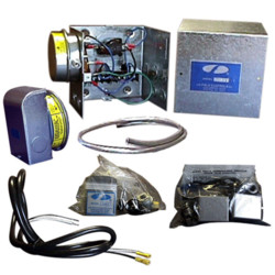
0000535708 00000 n
! !P;-.^nM/knqA* `qFl* dzu1^_
030p|nP#o9x95iF nbm1a(7@ H6
pcm fixya 
Wiring Diagram for CK-40 Series PVG or CAS Series for 24 Volt Gas Boiler; models CK-40, 40F, 41, 41F, 42, 43F, 44, 44F, PVG, CAS-4Jr., CAS-6, and CAS-7. Wiring diagram, shows wiring schematic of Fresh Air Ventilation Control (FAVC) Wiring Diagram for AprilAire Model 60 Humidistat and AprilAire Model 600 Humidifier. %PDF-1.4
%
English. 0000339001 00000 n
English.

Basic wiring diagram for 24v damper. English. English. Wiring Diagrams for CK-90 Series (CK-90, 91, 91F, 92F) for 24 volt Gas Furnace and 30mV Gas Water Heater (Co-Venting). 0000537775 00000 n
102 0 obj
<>/Filter/FlateDecode/ID[<62D4A45EE0078ACED9F16BBFC8DC90D9><92A7A6F7517BFB4393F9D888E2C18066>]/Index[83 32]/Info 82 0 R/Length 93/Prev 1523621/Root 84 0 R/Size 115/Type/XRef/W[1 2 1]>>stream
English. 0000000772 00000 n
English. Wiring Diagram fro models CAS-4, CAS-4Jr., 6, and 7 Chimney Vent, 24 volt Gas Appliance with 30mV Water Heater with CK-20F.

 Sitemap 29