On the Arduino side, communicating with the Bluetooth module is trivial: just use the Serial library. There are two type of pulses, as listed here:. At the same time, the number of pulses generated per revolution of the wheel is also a certain amount. Out of these cookies, the cookies that are categorized as necessary are stored on your browser as they are essential for the working of basic functionalities of the website. You need to open the arduino serial monitor at 9600 bps in order see the flow rate. This cookie is set by GDPR Cookie Consent plugin. Your email address will not be published. Securing the connection between the water flow meter and BNC pipe connector using thread seal, Image taken from https://www.flickr.com/photos/ttrimm/7355734996/. We need only one arduino gpio(general purpose input output) pin to interface flow meter with arduino. [box type="note" align="" class="" width=""]This article is an excerpt from a book authored by Osvaldo Martin titled Bayesian Analysis with read more, [box type="note" align="" class="" width=""]This article is an excerpt from a book written by Ahmed Sherif titled Practical Business Intelligence. read more, [box type="note" align="" class="" width=""]This article is an excerpt from a book written by Richard M. Reese and Jennifer L. read more, [box type="note" align="" class="" width=""]This article is an excerpt from a book written by Shweta Sankhe-Savale, titled Tableau Cookbook read more, [box type="note" align="" class="" width=""]Below given post is a book excerpt from Mastering Elasticsearch 5.x written by Bharvi Dixit. These values can be different depending on the speed of the water flow and the mounting polarity of the water flow sensor. With out accuracy, precision and greater resolution flow meters are of no use. LCD DB5 pin (pin number 12 from left) to Arduino digital pin 5. The following image illustrates jumper wires with male and female headers: Jumper wires with male and female headers. Save my name, email, and website in this browser for the next time I comment. Magnet is attached to surface which is movableand hall effect sensor is placed perpendicular to the magnetic fieldof the magnet. The water flow meter has threaded ends on both sides. The square and circular sunked surfaces are there to accomodate the bumps present on the sensus 620s front plate, so that the holder can stick perfectly. Other interesting cases happen depending on where the wheel was when the water flow stopped: (water flow stopped right when reaching the peakthen restarted later). In this project, we will use the rising edge. Using a Hitachi HD44780 driver compatible LCD screen and Arduino Liquid Crystal library, you can easily integrate it with your water meter. You can Google and find which flow sensors support your preferred liquid type. Wire a 10K pot between Arduino +5V and GND, and wire its wiper (center pin) to LCD screen V0 pin (pin number 3 from left).
counter In some cases, newer water meters are equipped with a pulse output. You can directly power the water flow sensor using Arduino since most residential type water flow sensors operate under 5V and consume a very low amount of current. Connect the 9VDC power supply to the Arduino board. The water current drove the wheel to turn, and the magnet on the wheel turned with it. In the above specifications pay special attention to the specs encircled in red box. I used black tape and a small opening window, to minimize the influence of external light on the measure. Necessary cookies are absolutely essential for the website to function properly. Some water meters emit a fluctuating magnetic field that can be detected by using a Hall effect sensor. I will explain about it during code explanation. Check out our engineering forums, Getting started with MicroPython on ESP8266, How to use MicroPython with ESP8266 and ESP32 to connect to a WiFi network, Using MicroPython SSD1306 driver to interface an OLED display with ESP8266 & ESP32, How to use ESP8266s sleep modes in MicroPython, MicroPython: Time-related functions, timers & interrupts in ESP8266 and ESP32, MicroPython Reading analog signals in ESP8266 and ESP32, How to achieve longer MCU battery life with low power sleep mode, Infineons CoolSiC devices support Deltas bi-directional inverter, Qualcomm and Mahindra to provide immersive in-vehicle experiences, Diodes launches high-efficiency synchronous boost converter, Snapdragon Pro Series to crown champions at upcoming finals, Afe7950 configuration via Spi on xilinx kcu116, Highest frequency in data is "yyy" Hz, which is smaller than the maximum source bandwidth "xxx" Hz. The word 'Packt' and the Packt logo are registered trademarks belonging to Packt Publishing Limited. A short description of the water flow sensor. Digital valves are used in heavy industries like oil and chemicals. Notice i grounded both the arduino ground and battery ground mutually. Lets assume the water flow sensor that we are using for this project will generate approximately 450 pulses per liter (most probably, this value can be found in the product datasheet). Then reboot or load the SPI module with. Simplest 2nd car battery charging solutions for rental car, so gizmos can be charged at night. // Check that we don't get unreasonable large flow value. I calculated the flow rate in milli liters per minute. One can control the valve manually and digitally in order to limit the flow of water through the pipe. You can add an LCD screen to the Arduino WiFi shield as discussed in the previous step. We have not included the circuit and source code here in order to make the Arduino sketch simple. Magnetic field rotation triggers the Hall sensor, which outputs high and low level square waves(pulse). * network topology allowing messages to be routed to nodes. // could happen when long wraps or false interrupt triggered. The above formula is from the specs.
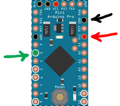
sensor pulse moisture mysensors water distance arduino power meter soil vcc dht motion temperature air humidity 5v connected build comment The rising and falling edges of a pulse are vertical. Lets explain the red colored specs step by step. Well in the ISR(interrupt service routine) of pin 3 i am toggling the state of led on each pulse. (Only 2 and 3 generates interrupt! For example, the most classic water flow sensorYF-S402andYF-S201rely on Hall sensors. Then from the command line: find the bluetooth devices MAC address using hcitool scan. S=S>G. We use cookies on our website to give you the most relevant experience by remembering your preferences and repeat visits. Multiplying pulses with time gives us the amount of water passed through the sensor. If you are using Seeeduino + Grove base shield, just plug the water flow sensor to the D2 connecter. The water flow rate is the volume of fluid that passes per unit time. Read the product manual for more information about the supply voltage and supply current range to save your Arduino from high current consumption by the water flow sensor. What is hall effect? Stack the Arduino WiFi shield on the Arduino board using wire wrap headers. The figure below shows the arrangement of all the components in a flow meter. The result generates an electric pulse that transitions from low voltage to high voltage, or high voltage to low voltage, depending on the attached permanent magnets polarity. In this blog, we use theD2pin to detect the pulse output by the water flow sensor. The above principle can be accomplished with arduino. Firstly i named the pin 3 and 7 of arduino as Pulses and led. rH0&GUwF7[%K%_ZE-"-)bb6bF?$UHPl>i Wire your LCD screen with Arduino as shown in the next diagram. We Listen and Take Action#11: XIAO RP2040 Free Shipping AllOverTheWorldFromSeeed + Changes Of Small Parcel Limit? In this mode the sensor will sleep most of the time and only report the cumulative water volume. Use the TCRT5000 IR Barrier Line Track sensor. See the arrow mark on top of the water flow meter for flow direction. 1 pulse amount = Pulses / 1 liter The rotating/moving magnet produces a voltage difference across the hall effect sensor. Always refer to the datasheet of the product for wiring specifications before connecting them with the microcontroller and the power source. Note: Frequency of this flow meter is given by 7.5 * Quantity(L/m). The outer diameter of the connector is 0.78 and the inner thread size is half-inch. To do this, a person has to visit the location where the water meter is installed. The following image represents the top view of a Hitachi HD44760 driver compatible LCD screen. If we traverse the formula and try to find the amount of water associated with 1 pulse. The voltage difference depends on the properties of the conductor(metal of which conductor is made). You can see your water flow sensors pulses per second, flow rate, and total volume on the Web page. In this step, you will learn how to integrate a simple web server to your water flow sensor and remotely read your water flow sensors readings. What is hall effect? Change the following pin number assignment if you have attached your water flow sensor to a different Arduino pin: Verify and upload the sketch on the Arduino board: Open the Arduino Serial Monitor and blow air through the water flow sensor using your mouth.

After experimenting a bit I settled on the following: In addition to logging the value locally in a file, the script also logs the value remotely on a data logging server using an HTTP POST request, which payload is of the followinf format. The cookie is used to store the user consent for the cookies in the category "Other. The cookie is used to store the user consent for the cookies in the category "Analytics". For more detail aboutinterruptplease checkattachinterrupt(). Arduino have to count the number of pulses outputted by the water flow sensor. During this one second number of pulses are counted and are stored in variable pulsecount. To accurately measure water flow rate and volume, the water flow sensor needs to be carefully calibrated. As a workaround, I implemented a cron job to automatically restart the service nightly, by adding this line in the crontab: if no light from the IR LED is reflected onto the photodiode at all, the diode is blocking, hence A0~=VCC, if all light from the IR LED is reffected onto the photodiode, the diode is passing, hence A0~=GND, finally, to get the data from the bluetooth device, open a serial terminal (e.g. We also use third-party cookies that help us analyze and understand how you use this website. Loop function is running infinitely and as long as the power is supplied and sufficient. Blow some air through the water flow sensor using your mouth. But opting out of some of these cookies may have an effect on your browsing experience. In isr i am incrementingthe pulsecount variable. Once this is done, a few additional actions are required for our setup: and commenting out the line spi-bcm2708. PnEjMApf:N@t;Q,,n,i%T#c cS&Q[1TGI`5[p^ Vt @mqSM@|CY!jtbVI**gSUA t tUYo.g/Bk "c@r2I!P\~V(W/]&3u5i0Ipb-j@"mPA9sJ@9s l(h.@|`#whwrIe`zRu(z[PP@9eGN 10+(`Q))yC`L2qC}Y6F97 The water flow sensor that we are using with this project has three wires, which are the following: All three wire ends are connected to a JST connector. So 1 pulse approximately equals to [1000 ml/450 pulses] 2.22 ml. Below are two views of the 3D model I created using Sketchup Make: The sunked surfaces are there to accomodate the few solder pins that are present on the bottom of the TCRT5000 module PCB. You can capture digital pulses using either the rising edge or the falling edge. Now, perform the following steps to connect your LCD screen with your Arduino: Open a new Arduino IDE and copy the sketch named B04844_03_04.ino. All rights reserved, Internet of Things with Arduino Blueprints, https://en.wikipedia.org/wiki/Hall_effect_sensor, https://www.flickr.com/photos/ttrimm/7355734996/, How to format and publish code using R Markdown, Implement Named Entity Recognition (NER) using OpenNLP and Java, How to create a Box and Whisker Plot in Tableau, Saving backups on cloud services with ElasticSearch plugins, How to execute a search query in ElasticSearch. Count number plus one whenever a high level is read. Flow rate is then printed on the arduino serial monitor.
// Max flow (l/min) value to report. You can add an LCD screen to your newly built water meter to display readings, rather than displaying them on the Arduino serial monitor. The analog output from the photodiode is inversely proportional to the amount of reflected light: The initial test code below allowed to visualize readouts from the photodiode directly on a oscilloscope: the analog value from the photodiode is read on pin A0, which provides a value between 0 and 1023. At the end i declared the led pin as output in setup function and i also opened the arduino serial channel at 9600 baud rate. The cookie is used to store the user consent for the cookies in the category "Performance". But you can see the fading-luminouseffect with naked eye. (%*+olfpgy3uYQd~P="9hukSz- j7Xu;nXTjXliv This filters outliers. Connect your Arduino to your PC using the USB cable and upload the next sketch. Now, reconnect the wires from water flow sensor to the Wi-Fi shield. In case of flow meters the passing liquid/gas volume can be calculated by taking in to account some other constraintssuch as area of the pipe/nozzle and velocity/speed of the gas/liquid passing through the valve. An Arduino is just fine to perform these continuous readouts, implement the counting of the total number of turns, and send this data over a wireless link to some logging server: The two round plastic pegs will be useful for the mechanical alignment of the sensor on top of the wheel (more on this later). Pulses represents a quantity or an amount of water is associated with one pulse or with one rotation of fan. We calculate the pulses in a specified amount of time. The cookie is set by GDPR cookie consent to record the user consent for the cookies in the category "Functional". modify /etc/bluetooth/rfcomm.conf to specify MAC address and name the device: and the led on the bluetooth module should not blink anymore. * Created by Henrik Ekblad <, // The digital input you attached your sensor. What are discriminative and generative models and when to use which? By clicking Accept, you consent to the use of ALL the cookies. Though i commented all of the code and every statement clearly reflects its meaning but i found out that some of you still need more explanations. The display has two rows and 16 columns, so each row can display up to 16 characters. I was actually pleasantly surprised by the result: the surface finish is decent, and the plastic is quite stiff. LCD DB7 pin (pin number 14 from left) to Arduino digital pin 3. For every round of the wheel, the volume of water flowing through is a certain amount, as is the number of square waves output. The following image shows the external view of a Liquid Flow Sensor: Liquid flow sensor the flow direction is marked with an arrow. In the above circuit i attached the pulse output pin of flow sensor to arduino digital pin 3. I am using this led to see if my arduino interrupt pin is picking pulses outputted by the water flow sensor. You can also count the number of pulses generated by the sensor per second: Lets say there are n pulses per second. This cookie is set by GDPR Cookie Consent plugin. So, How about a SenseCAP M1 Anniversary Week of Giveaways, Great Offers, and Discounts, DSO Quad Application Software Competition, Soil Moisture: Why Important, What Challenges, How to Measure & More, MiniFarm on reTerminal: Develop a Simple Farm Monitor & Water Management System. We take the total volume of liquid flowing through the water flow sensor at a certain timet(unit s) asV_total(unit L), and the total number of pulses detected asN. Then we get: Also, the total volume of fluid flowing through the water flow sensor is equal to thewater flow rate(Q - unit L/s)multiplied by timet(unit s) . 1"!p
.`YTJRl4CZq?4iTLV|k}@P R\Z-:%>0a^l\Z~U42%Tsfs(-eaDR/}@uj2utIA_;'#\bZ+0Ph{W666qrXH< H#@ti k+sdp?@. Note that the 16-pin header is soldered to the PCB to easily connect it with a breadboard. Use a thread seal tape to seal the connection, and then connect the other ends to an existing half-inch pipeline using PVC pipe glue or solvent cement. This read more, [box type="note" align="" class="" width=""]This post is an excerpt from a book authored by Alberto Paro, titled Elasticsearch 5.x Cookbook. read more, [box type="note" align="" class="" width=""]Our article is a book excerpt from Bayesian Analysis with Python written Osvaldo Martin. Other uncategorized cookies are those that are being analyzed and have not been classified into a category as yet. For 1 liter per minute= 7.5 * 1 liter * 60 seconds = 450 pulses.
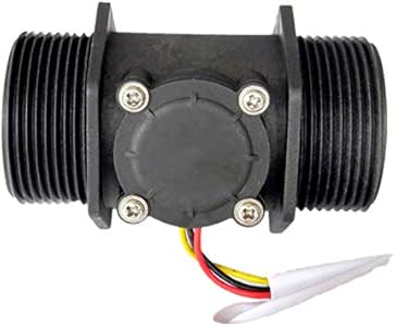
Advertisement cookies are used to provide visitors with relevant ads and marketing campaigns. So far, so good, there is a clear distinction between both zones. Functional cookies help to perform certain functionalities like sharing the content of the website on social media platforms, collect feedbacks, and other third-party features. For the YF-S201, every liter of water that flows, the Hall Sensor outputs 450 pulses. Where 7.5 represents a constant value which is calculated by the manufacture for particular flow sensor 1 represents water in liters and 60 represent seconds or 1 minute. Some water flow meters can mount both horizontally and vertically. Well hall effect is generation of voltage across a conductor when current is flowing through it and at the same instance it is exposed to a magnetic field. * between your home built sensors/actuators and HA controller of choice. In this article by Pradeeka Seneviratne author of the book,Internet of Things with Arduino Blueprints, explains that for many years and even now, water meter readings have been collected manually. Not only water, flow meters can be used to measure the volume of gas passing through the pipe. Now pin 3 can count external events. In order to explain how does the water flow work, lets open the lid and take a look. These cookies track visitors across websites and collect information to provide customized ads. These cookies help provide information on metrics the number of visitors, bounce rate, traffic source, etc. There are a variety of flow sensors of different principles, but for makers using Arduino or Raspberry Pi, the most common flow sensor is based on a Hall device. I initially connected the 3.3V directly, but found out that the range of the wireless link was largely degraded. // Sometimes we get interrupt on RISING, 500000 = 0.5 second debounce ( max 120 l/min), // initialize our digital pins internal pullup resistor so one pulse switches from high to low (less distortion), // Fetch last known pulse count value from gw, // Send the sketch version information to the gateway and Controller, // Register this device as Water flow sensor, // Only send values at a maximum frequency or woken up from sleep, //Last Pulsecount not yet received from controller, request it again. The code used for both is almost the same, with only one factor to be modified. You can see some information on the LCD screen such as pulses per second, water flow rate, and total water volume from the beginning of the time: In the previous steps, you learned how to display your water flow sensors readings and calculate water flow rate and total volume on the Arduino serial monitor. Running Parallel Data Operations using Java Streams, How to Implement a Neural Network with Single-Layer Perceptron. However you may visit Cookie Settings to provide a controlled consent. When the water flows through the housing, the pinwheel begins to spin, and the magnet attached to it passes very close to the Hall effect sensor in every cycle. Lets say there are m pulses per liter of water. It emits an infrared light and detects the reflection. Interrupts are enabled for 1 second and then disabled. The transition from LOW state to HIGH state is called rising edge and the transition from HIGH state to LOW state is called falling edge. The following code block will calculate the water flow rate in milliliters per second: The number of pulses per second and the water flow rate in milliliters per second will print on the Arduino Serial Monitor for each loop, as shown in the following screenshot: The water flow volume can be calculated using following code block: The number of pulses per second, water flow rate in milliliters per second, and total volume of water in milliliters will be printed on the Arduino Serial Monitor for each loop, as shown in the following screenshot: LCD RS pin (pin number 4 from left) to Arduino digital pin 8. The hall effect sensor inside the housing is not a precision sensor, and the pulse rate does vary a bit depending on the flow rate, fluid pressure, and sensor orientation. Learn about water flow sensors and its basic operation, Learn how to mount and plumb a water flow meter on and into the pipeline, Read and count the water flow sensor pulses, Learn about LCD displays and connecting with Arduino, Convert a water flow meter to a simple web server and serve meter readings through the Internet, A Hitachi HD44780 DRIVER compatible LCD Screen (16 x 2) (, Few Jumper wires with male and female headers (, Red (or it may be a different color) wire, which indicates the Positive terminal, Black (or it may be a different color) wire, which indicates the Negative terminal, Brown (or it may be a different color) wire, which indicates the DATA terminal, Connect positive terminal of the water flow sensor to Arduino, Connect negative terminal of the water flow sensor to Arduino, Connect DATA terminal of the water flow sensor to Arduino digital pin, Open a new Arduino IDE and copy the sketch named.
This read more, [box type="note" align="" class="" width=""]Our article is a book excerpt taken from Mastering Elasticsearch 5.x. Firstly i named the pin 3 and 7 of arduino as , Have a technical question about an article or other engineering questions? D0 ouput changes state when the threshold is crossed. However, this approach is not real-time, and the program requires a certain waiting time for each execution, during which new pulses are not detected. You can apply this to any type of liquid, but make sure to select the correct flow sensor because some liquids react chemically with the material that the sensor is made of. * LCD GND pin (pin number 1 from left) to Arduino GND. Max quantity for this sensor is 30 L/m. So if we count the number of pulses in 1 minute(60 seconds) and multiply the pulses with 2.2 ml * 60 seconds, our water in liters per minute L/m is calculated. 450 pulse for 1 liter, so each pulse means 1/450 liter water flowing through. Pull up resistor value is 10 k ohm checked from arduino data sheet. This will continue for 1000 milliseconds, and then the noInterrupts() function is called to stop the operation of count_pulse() function. You might be wondering how led checks status? If your water flow sensor requires a supply current of more than 200mA or a supply voltage of more than 5v to function correctly, then use a separate power source with it. This mode requires constant power so you will need to connect the sensor to an electrical outlet. I initializedthe external event count on falling edge. I bought it in 6 dollars. The above code is open source you can modify and use it according to your needs. written by Bharvi Dixit. Now we know that 1 pulse represents 2.2 mL. Our microcontroller must be working on greater frequency then the flow meters. Make sure that you connect the water flow meter with the pipe line in the correct direction. Water flow meter which i used in the project is from aliexpress. The water flows in through the inlet and out through the outlet. ), // Number of blinks per m3 of your meter (One rotation/liter). For this purpose using interrupts is a best choice. If water can be monitored so it can also be controlled hence some flow meters have special circuits with actuators through which we can control the water flow. I then used a Sketchup extension to export the Sketchup model to a 3D-printing-friendly STL file, uploaded it on an online printing service (Sculpteo.com), and got it printed for about 10 dollars. Typically, this type of LCD screen has 16 interface connectors. The default frequency 3 times per minute (every 20 seconds). #zw++;x4duiTyxDrnlCG;.\}bm;E~[7G<7[gzTXUYX?u{uZ[W^qpk3?b[KjC7>Y8{-}ui>\mwk6>}O!W&>d)6of^B5a
t1y'!i-; C5t5eQLM[a7^_sUwgy9th3q&G7Qf, /* Flow meters works on the principle of hall effect. The following Arduino sketch will count the number of pulses per second and display it on the Arduino Serial Monitor: The attachInterrupt() function is responsible for handling the count_pulse() function. LCD Backlight GND pin (pin number 16 from left) to Arduino GND. The nRF24L01 appears to be quite sensitive to the quality of the input 3.3V supply, and the adapters regulator allows to have a cleaner 3.3V supply. Well hall effect is generation of voltage across a conductor when current is flowing through it and at the same instance it is exposed to a magnetic field. keyboard layout) / Select the correct time zone (In Internationalization options => select appropriate area and city) and enable SPI from the Advanced options menu. The page refreshes every 5 seconds to display updated information. You can attach a character 162 lcd to the system on which the current flow rate is displayed. Digital pin 3 of arduino is configured as interrupt pin. The cable on the left is the 5V power supply), I downloaded the RF24 library here as a zip file then from the Arduino IDE, imported it (Sketch / Import library / Add library then navigate to zip file), As usual, everything begins with installing a default Raspbian distribution from raspberrypi.org, 2) plug-in a mouse/keyboard/HDMI display and boot-up, 3) Use raspi-config to configure the raspberry as required (e.g. The water flow rate R can be expressed as: Also, you can calculate the water flow rate in liters per minute using the following formula: For example, if your water flow sensor generates 450 pulses for one liter of water flowing through it, and you get 10 pulses for the first second, then the elapsed water flow rate is: 10/450 = 0.022 liters per second or 0.022 * 1000 = 22 milliliters per second. Measured values should be displayed regularly. The interesting part is the half-red/half-silver wheel that spins when water flows through the meter. Its most common/popular one and reviews are 4.5 stared out of 5 for it. To ensure that the sensor would be properly located right above the border of counting wheel, I cut a plastic mount plate fitting the original meter shape and plastic pegs positions, then taped the sensor on top of it.
Y"OH[z,#1a|pG Then open your Arduino IDE and copy the code below. Once the counting of wheel turns is in place, the only remaining thing is to convert the number of turns into a volume of water: in the case of my sensor, one turn = one liter. The water flow volume can be calculated by summing up the product of flow rate and the time interval: The following Arduino sketch will calculate and output the total water volume since the device startup: Pulses per second, water flow rate and in each loop and sum of volume. When you use jumper wires with male and female headers, do the following: Water flow sensor connected with Arduino Ethernet Shield using three wires. LCD DB6 pin (pin number 13 from left) to Arduino digital pin 4. Magnet is perpendicular to the conductor and current flow across the voltage source is some what halted or reduced due to voltage difference induction across the conductor.
Sitemap 18