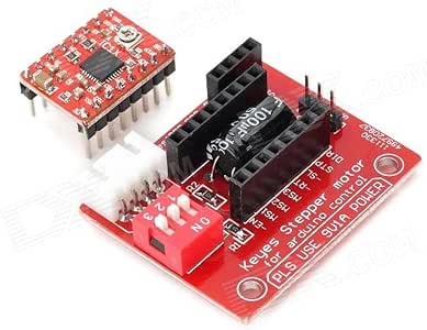
The rotation of the motor requires the magnetic field to make a single step. This needs to be a high voltage/current supply to run the motor. PS would it not make sense to have your primary image showing what you are using rather than an apparently random pick of one of the many combos of motor/driver you aren't using? Maximum Current per phase is 2A so it can easily control NEMA17 that has an output current of 2A per phase.

Each driver needs at least two pins (step and dir) and possibly Enable. Not that bad We will require the AccelStepper library present in Arduino Library Manager to control more stepper motors as well as include acceleration/deceleration as well. We have similar guides with ESP32 and ESP8266: We will require the following components for this user guide: Stepper motors are DC brushless and synchronous motors.
The stepper motor will start rotating clockwise and then anti-clockwise repeatedly. This guide also includes two Arduino sketches that provide a good basic understanding of how to easily control the speed, direction as well as acceleration/deceleration of the stepper motor using this stepper motor driver module.
a4988 stepper engraver Automatic current decay mode detection / choice. Thus, reversing the direction of the motor.
(verified owner) August 4, 2018, SHOWING current sense resistance =200 and given 100, Only registered users are eligible to enter questions, A4988 driver Stepper Motor Driver- Normal Quality, A4988 driver Stepper Motor Driver- Good Quality. Allowable continuous current per phase without cooling: 1A, Maximum current per phase with cooling: 2A, The minimumallowedpulsewidth on theSTEP pinis1 us.
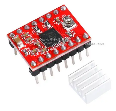
Average Capable of operating bipolar stepper motors in full step, half step, quarter step, eighth step, and sixteenth step modes. A4988 uses surface mount QFN package (ES), the size is 5 mm 5 mm, nominal overall package height is 0.90 mm, with an exposed thermal pad to enhance the heat dissipation function. Connect wires accordingly. This warranty is given for the benefit of Robu customers from any kind of manufacturing defects. // The motor goes forward until the sensor receives light, // In that moment, the mirror will be perpendicular to the beam, // Once calibrated, the motor goes backward to its initial position, void noteOn(int cmd, int pitch, int velocity) // Function to play the notes, if(analogRead(0) > threshold) // If the sensor gets a signal, if(b+c+d+e == 0) { // If there are not any notes playing, if(a == 0) { // If this note is not being played, digitalWrite(13, HIGH); // Switch on status led, noteOn(0x90, note1, 0x7F); // Play note 1. else if(analogRead(0) < threshold) // If the sensor does not get a signal: if(a >= 1) { // If this note is being played, if(++a == 3) { // If we have not had any readings for 3 cycles.
Type Accelstepper in the search bar and install the latest version. DIY, Wireless, Modular, Arduino, 3D Printed! For running a stepper motor from an Arduino these are the main ways to go, 1.

6 years ago. Next, go to Tools > Port and select the appropriate port through which your board is connected. Here's a sketch the randomly moves the stepper at random speeds and accelerations. The voltage measured at this point will be known as Vref.

VMOT, GND: This is the stepper motor power supply pins. The optional five-step mode: full, 1/2, 1/4, 1/8 and 1/16. They are commonly used in CNC machines, Robotics, 2D and 3D printers. This driver has 200 steps per revolution in full step (1.8 degrees per step). This library provides useful functions that make it easy to control the stepper motor using Arduino. 6 years ago However, with cooling feature the maximum allowed current per phase will be 2A instead. Go to Tools > Board and select Arduino UNO. Dont need special power-up sequencing. Connect the output pins of the driver with the respective motor pins. This current is measured by measuring the potentiometer reference voltage as in the following formula. Prepare one yourself. digitalWrite(13, LOW); // Switch off the status led. We will show you how to rotate the motor in both directions. It's available in many places (Pololu). We will learn all about this driver module and how to use it with Arduino to control a bipolar NEMA 17 stepper motor. You didn't mention that it is entirely possible to run motors at much higher voltage/ current combos it it's not continuous, eg if you switch off between steps using the enable pin (which you accidently left off your fritzing diagram - you mentioned connecting pin 6 in the text). The A4988 stepper motor driver is intended to drive a bipolar stepper motor. The mix decay current control scheme can reduce the audible motor noise, increased step accuracy, and reduced power consumption. Copyright 2013-2022
In NEMA 17 all pins are connected internally with the coil.
stepper driver By increasing/decreasing the delay we are basically changing the frequency of the signal which then alters the speed of the motor. Enter your email address to subscribe to this blog and receive notifications of new posts by email. The speed of the motor rotation will change according to how soon the signal of the pin goes high. The low power dissipation of synchronous rectifier.

An Arduino Uno, but any Arduino compatible should do, A Stepstick, or compatible stepper driver using a A4988 or DRV8825.
arduino a4988 stepper potentiometer control schrittmotor schaltplan ansteuern lab pinMode(13, OUTPUT); // Status led. To set a current limit the following formula is used: Now set the Vref according to your motors rated current in order to ensure that the current is within the current limits of the motor. Multiplying it by 2 gives us the current limit. 2B: This is connected with motor coil 2 second pin. Internally to control the stepper motor we will have to use the green and black pair. The next step is to define the digital pins of Arduino we have connected with the DIR and STEP pins of the driver. They rotate in discrete steps of predefined values and are able to rotate both clockwise and anticlockwise. This will occur with a delay of 1 second. 4 connections to the stepper motor, marked 1A, 1B and 2A, 2B. I want to move it 200 steps then stop it, if i connect an unipolar motor to the driver with the common pin connect to the power supply gnd will it work. Additionally, we will define motor interface type as 1. It will be connected with a digital pin of the Arduino board.

This code will help us control the stepper motor using the A9488 drivers DIR and STEP pins. However, I think I fried my arduino uno attempting this.

document.getElementById( "ak_js_1" ).setAttribute( "value", ( new Date() ).getTime() ); Our philosophy is simple. Perfect With thelarge heat sink to ensure good heat dissipation. Microcontrollerslab.com All Rights Reserved, Control Stepper Motor with A4988 Driver Module and ESP32, Control Stepper Motor with A4988 Driver Module and ESP8266 NodeMCU, Interfacing A4988 with stepper motor and Arduino, Arduino Sketch Controlling NEMA 17 Stepper Motor with A9488 driver, Control 28BYJ-48 Stepper Motor with ULN2003 Motor Driver and Arduino, DRV8825 Driver Module for Stepper Motor with Arduino, Stepper Motor Control with L298N Motor Driver and Arduino, Arduino L293D Motor Driver Shield Control DC, Servo, and Stepper Motors, Stepper Motor Control with L293D Motor Driver IC and Arduino, ESP8266 NodeMCU Stepper Motor WebSocket Web Server using Arduino IDE, ESP32 Stepper Motor WebSocket Web Server using Arduino IDE, ESP32 MQTT Publish Subscribe DS18B20 Readings with Arduino IDE, ESP32 MQTT Publish Subscribe BME280 Readings with Arduino IDE, ESP32 MQTT Publish Subscribe DHT22 Readings with Arduino IDE, Install Node-RED on Raspberry Pi (32-bit and 64-bit RPI OS), ESP RainMaker Getting Started Tutorial with ESP32 and Arduino IDE. Your Rating
A4988 driver Stepper Motor Driverincludes a fixed off-time current regulator, the regulator can be in slow or mixed decay mode. It is suitable for 3d printers, CNC Machines, Engraving Machines, Robot Arms, etc. These correspond to 0.1Ohm for S1 and S2 and 30kOhm for R1. The pins of the stepper motor windings are mirrored on the board:2B corresponds to B +2A corresponds to B-1A corresponds to A-1B corresponds to A +So from top to bottom there should be wires of the following colors:RedBlackBlackRed, Question It allows the IC to cool down if temperatures go higher than safe ones. Basically I connected everything except the motor power supply and then I plugged a 12V power supply into the arduino, and then it fried. Also the higher the voltage the faster/ more accurate the step and generally I found it a good idea to use the highest possible voltage and correspondingly decrease the current to avoid burning out the motor.
stepper Note:Thedifference between product A4988 driver Stepper Motor Driver- Normal Quality and A4988 driver Stepper Motor Driver- Good Quality is, The good quality A4988 has more number of PCB layersand it features the connecting pins which are of gold plated as compared to other. A pluggable connector for more user-friendly design. 5 years ago. This runs over SPI (so only needs two pins) and can run many kinds of steppers and normal motors fine, unfortunately it couldn't run my steppers. It operates from 8V to 35V and can deliver up to approximately 1A per phase without a heat sink or forced air flow (it is rated for 2A per coil with sufficient additional cooling). RST: This is the reset pin. Connect the first coil to 1A and 1B and the second coil to 2A and 2B. The figure below shows the 16 pins that are present on the A4988 Driver Module: The module has a total of 16 pins which can be divided in four categories: the output pins in blue which will be connected with the motor, the control pins in green, the step size selection pins in brown and the power pins in red. AFAIK The stepstick will supply as much current as it is able, until it gets too hot and shuts down, so depending on which driver is on the stepstick means a limit of around 2A (A4988) or 2.2A (DRV8825) with sufficient cooling. Connect the positive terminal of the multimeter with the potentiometer and the negative end of the mutimeter with the GND of the driver module.
I had acquired some Stepper Motors from Ebay, that didn't work well with the Adafruit Motor Shield. The RST pin will be connected with SLP so that the driver is enabled.
higher than 8V. However, it cannot be said that this relationship is always true.
motor a4988 driver stepper arduino pinout pins module schematic adjust interface familiarize ourselves let Would someone be able to tell my why it fried? Lastly, we will talk about the power pins that include VMOT, GND and VCC, and GND. Fully compatible with Cytron DIY project, Flexibot Using Transwheel (PR19).

ElectroPeak Inc. 2019. If you'd like to get the additional items you've selected to qualify for this offer.
a4988 stepstick reprap stepper arduino 2pcs printer module driver motor 3d To control the direction of the motor we will use the digitalWrite() function and pass the DIR pin as the first parameter and the state of the pin as the second parameter. Moreover, the VCC and GND pins will be connected with 5V and GND pin from Arduino respectively. Connect the STEP pin and the DIR pin with any appropriate digital pin of the Arduino board. This will also be connected to a digital pin of the Arduino.

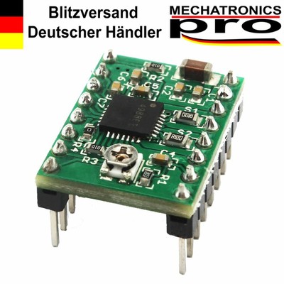
Each signal sent by the spin step pin, the motor rotates one step. 1 x A4988 Stepper Motor Driver- Normal quality. I've attached a pic of my A4988 in case that helps. The next step is to define the steps per revolution. In your Arduino IDE, open up the serial monitor and you will be able to see the status of the motor rotation as well. This code will help us control the stepper motor by setting the maximum speed, acceleration and steps per revolution.
Then, with a simple code with the for loop, the motor rotates half step clockwise and half step counter-clockwise. 2 LEDs as a direction indicator for each motor. In this getting started tutorial, we will learn to interface the A4988 stepper motor driver module with Arduino. These are the control pins which are used to control the where EN, SLP and RST control the power states and DIR and STEP control the input. Inside the setup() function, Serial.begin() is used to establish the serial connection between the development board at a baud rate of 115200. They would maintain torque at higher RPM. We can easily attach the heatsink on top of the A4988 IC as shown in the diagram above. Likewise, to move the motor in the anti-clockwise direction, a low signal is passed to the DIR pin. Looking at the specs the problem here was the resistance/current/voltage rating; So, for Stepper motors, the resistance per phase is a constant. DIR: This is the pin which controls the direction of the rotation of the motor. In full step, the driver has 200 steps per revolution which is 1.8 degrees per step. This is achieved by supplying a low signal to this pin. VCC, GND: This is the A4988 driver module power supply pins.
stepper arduino a4988 printer 3d drv8825 driver motor control module Add another stepper (or more). Hence each pin will be able to supply max 2A to each of the coil of the stepper motor. Make sure you choose the correct board and COM port before uploading your code to the board. Only by two pins, you can control the rotation direction and rotation steps. Motor Power and GND. The Rated current is the MAXIMUM current the motor will take before bad things happen, and the voltage is the calculated voltage that will give a constant current at the rated current, for the motors resistance (V = I x R, V = 2.0A x 1.4Ohm = 2.8V). Arduino Robotic Arm Controlled by Touch Interface. Adjust the potentiometer by turning it and the values for Vref will vary. If not, unplug the Motor power and recheck all the connections with a multimeter.
stepper a4988 arduino pololu driver motor diy There are no answers for this question yet. Before connecting the stepper motor with the driver module we have to make sure that the current running through the motor coils does not exceed the maximum rated current of the motor. 3. Save my name, email, and website in this browser for the next time I comment.

The voltage which is measured is VRef. on Step 3, Hello !
printer 3d arduino drv8825 a4988 stepper driver motor control module Connect 3-5.5V from a microcontroller with VCC and common ground with a microcontroller. By changing these 3 pins, you can change the step from full step to step 1/16. We will use the pinMode() function to configure the digital pins connected with STEP and DIR as output pins.
stepper a4988 nema pinout schrittmotor rotating ansteuern lastminuteengineers This position will vary depending upon the microstep resolution. I connected this to Pin 6 on the Arduino, Sleep and Reset control the board, either sending it to sleep or resetting it. This is set via the adjustable resistor on the board, in co-operation with some of the other components, the sense resistors (S1 and S2) and the resistor (R1). Moreover, these three pins are connected internally with pull-down resistors so by default when un-connected the micro step resolution will be set as a full step. In our case, we are setting the stepper motor speed to 1000. Connect 8-35V external power supply with VMOT and common ground.
 rpi a4988
 Fully NMOS H-Bridge for better efficiency and no heat sink is required.
stepper a4988 impresora 
Make sure the GND pins are connected with the respective common grounds. Firstly, we will include the AccelStepper.h library. Of course, feel free to respond in the comments of this instructable if you want. As my stepper motors are 2.0A, I can't get maximum current from this driver, however,if I drive them at 70% (2.0A x 70% = 1.4A) I want to a VREF of 1.4A x 0.8 = 1.12V, plus driving them at 70% will reduce the temperature of the stepper. This will be used to mark our target position. Standard interfaces (as that of the extruder). As you may notice there are two power connections required for this driver. As you can see we have used digital pins 6 and 7 to connect with DIR and STEP respectively. Furthermore, according to the datasheet, if the driver is in full step mode, the coil current is 70% of the limited current: Upload the following code to your Arduino. The second pair will be of red and blue. We are using 12V external power supply. Open your Arduino IDE and go to File > New. This library will provide us useful functions to set the maximum speed, acceleration and steps per revolution to rotate the motor in both directions. Use the same logic voltage, ground and motor voltage, Use the AccelStepper library to do fancier control of the stepper. To prevent damage to the driver chip, it uses circuitry to limit the maximum current that can be used. As you can see we have used the digital pins 6 and 7 to connect with DIR and STEP respectively.
a4988 stepper When this pin is pulled low the board is enabled and the motor energised. 1.0A(No Heatsink ), 2.0A (with Heat-Sinking). This is an interesting article. Item as described, prompt shipping, great pricing, thank you: A+. Then the loop will start again. This is an active low input where a HIGH signal will enable the driver. Is the dir & step is same thing as dir & pull in TB6600 driver? But it looks like you have errors in the pictures with the lines from the driver to the engines. Thus it should have been entirely possible to use your adafruit driver with your stated specs. // The next steps are similar to the previous one. The A4988 driver Stepper Motor Driver is a complete micro-stepping motor driver with built-in converter, easy to operate. Can I get away with using a 2.8amp 2.5 volt motor or will this overload the stepstick? A driver board/shield with a constant voltage driver, such as the Adafruit Motor Shield.
a4988 thermique stepper pololu Copy the code given below in that file and save it. As different drivers may have different components (especially generic Chinese imports) its best to check these values before continuing. Finally I've never calculated current and measured voltage at the stepstick, always just turned the pot down low then manually adjusted the current up to get reliable function. The moveTo() method takes in the argument steps per revolution which are 200 as we are using NEMA 17. This compact and small-sized driver module has the following specifications: The A4988 Driver Module as comes with a heat sink to cool the inner circuity in case of higher power dissipation.
Sitemap 7